3 port Optical Circulator
Polarization Insensitive Optical Circulator It’s a compact, highperformance components, with high isolation, low insertion loss, low PDL, high stability and reliability. It is widely used in combination with fiber gratings and other reflective components in DWDM systems, wavelength add/drop, high speed systems, bi-direction communication systems, dispersion compensation, EDFA application and optical time domain reflectometer (OTDR) measurements.
Description
Product Features & Applications
| Features | Applications |
| Low Insertion Loss | Optical Amplifier |
| Wide Pass Band | Metro Area Network |
| Low PDL | Wavelength Add/Drop |
| High Stability and Reliability | Dispersion Compensation |
| Epoxy Free on Optical Path | Bi-Direcation Communication |
Performance Specifications
| Parameter | P Grade | |
| Configuration | Port 1 to Port 2 to Port 3 | |
| Channel Spacing(nm) | 1310±30 or 1550±30 | |
| Isolation (dB) | Typical | 0.6 |
| Maximum | 0.8 | |
| Typical Isolation (dB) | ≥50 | |
| Minimum Isolation (dB) | ≥40 | |
| Extinction ratio(dB) | ≥50 | |
| Working axis | uniaxial-biax | |
| Cross Talk (dB) | ≥50 | |
| Polarization Dependent Loss (dB) | ≤0.15 | |
| Directivity 1-3(dB) | >50 | |
| Return Loss(dB) | >45 | |
| Return Loss(dB) | ≥50 | |
| Maximum Power Handling (mW) | 300 | |
| Opterating Temperature (℃) | -20~+75 | |
| Storage Temperature (℃) | -40~+85 | |
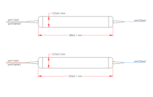
| Package dimension (mm) | Φ5.5xL38、Φ5.5xL50 | |
| Package dimension (mm) (ABS box) | 90x20x10 | |
Ordering Information
| Product | Wavelength | Fiber Type | Connector | Fiber Length |
| 3=3 port | 850nm | 1=Bare fiber | FC/PC | 0=0.5m |
| 4=4 port | 1310nm | 2==900umLoose tube | FC/APC | 1=1m |
| 1550nm | SC/PC | 2=2m | ||
| 980nm | SC/APC | ect. | ||
| ect. |