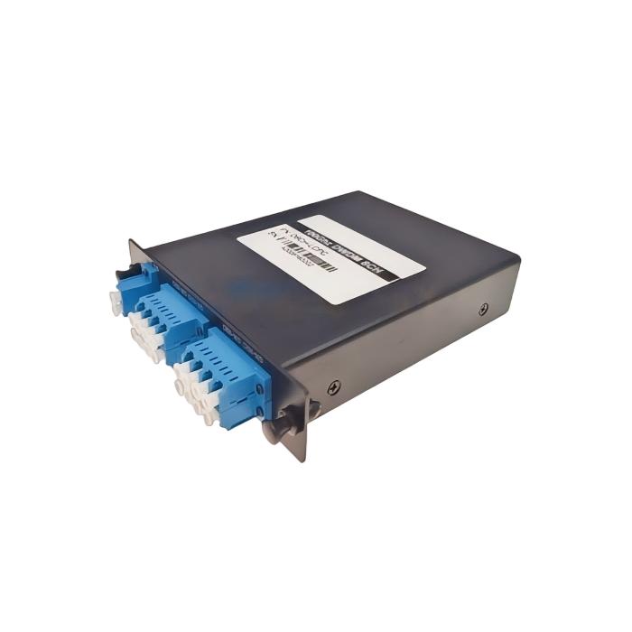
96-CH 50G Athermal AWG
This 96-Channel 50GHz Athermal AWG (Arrayed Waveguide Grating) module offers high-density wavelength multiplexing and demultiplexing with excellent thermal stability. Designed for operation in the C-band, it provides low insertion loss, high channel isolation, and reliable performance without the need for external power or temperature control.
Ideal for WDM networks, telecommunications, and access networks, the module supports 96 channels with precise wavelength stability. Its compact design and athermal characteristics ensure consistent operation across varying environmental conditions. Custom configurations including fiber type, connector options, and fiber length are available to meet specific system requirements.
Description
Features & Applications
| Features | Applications |
| Low Insertion Loss | WDM Network |
| Wide pass band | Telecommunication |
| High Channel Isolation | Access Network |
| High Stability and reliability |
Absolute Maximum Ratings
| Parameter | Conditions | Specifications | Unit | |
| MIN. | Max. | |||
| Operating Temperature | Non-Condensing Environment | -5 | 65 | ℃ |
| Operating Humidity | 5 | 85 | %RH | |
| Storage Temperature | Device Not Powered on Heater Element | -40 | 85 | ℃ |
| Storage Humidity | Device Not Powered on Heater Element | 5 | 95 | %RH |
Optical Specifications
| Parameter | Specification | Units | Notes | |||
| MIN | Typ | Max | ||||
| Channel Spacing | 50 | GHz | ||||
| Nos of Channel | 96 | CH | ||||
| Channel Frequencies | C-band | nm | ||||
| Clear Channel Passband | ±6.25 | Ghz | ||||
| Wavelength Stability | ±0.05 | nm | ||||
| Bandwidth @1.0dB | 0.2 | nm | ||||
| Bandwidth @3.0dB | 0.28 | nm | ||||
| Optical Insertion Loss at ITU grid | 1.2 | dB | ||||
| Adjacent Channel Isolation | 25 | dB | ||||
| Non-Adjacent Channel Isolation | 30 | dB | ||||
| Total Cross Talk | 20 | dB | ||||
| Insertion Loss Uniformity | 0.8 | 1.3 | dB | |||
| Directivity | 40 | dB | ||||
| Return Loss with connectors | 40 | dB | ||||
| Polarization Mode Dispersion | 1 | ps | ||||
| Chromatic Dispersion | -20 | +20 | ps/nm | |||
| PMD | 0.3 | 0.5 | ps | |||
| Maximum Input Optical Power | 500 | mW | ||||
Channel Plan 17 Port AWG – On Grid
The AWG operate in O-band. The channels are as follows:
| Channel No. | Frequency (THz) | Wavelength (nm) | Channel No. | Frequency (THz) | Wavelength (nm) |
| 1 | 233.6 | 1283.358 | 10 | 232.25 | 1290.818 |
| 2 | 233.45 | 1284.183 | 11 | 232.1 | 1291.652 |
| 3 | 233.3 | 1285.008 | 12 | 231.95 | 1292.487 |
| 4 | 233.15 | 1285.835 | 13 | 231.8 | 1293.324 |
| 5 | 233.0 | 1286.663 | 14 | 231.65 | 1294.161 |
| 6 | 232.85 | 1287.492 | 15 | 231.5 | 1295.000 |
| 7 | 232.7 | 1288.322 | 16 | 231.35 | 1295.839 |
| 8 | 232.55 | 1289.153 | 17 | 231.2 | 1296.680 |
| 9 | 232.4 | 1289.985 | 18 |
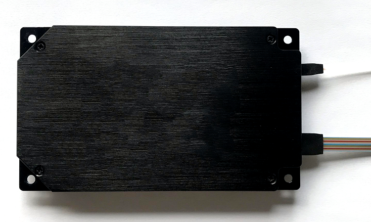
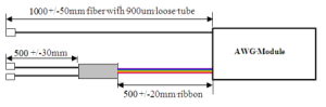
Mechanical Dimensions, Fiber Coding and Connector Specifications
| Parameter | Specification | Unit |
| Dimensions | 120 × 70 × 10.5 | mm |
| Fiber Type | • Common: SMF-28e, 900um tube • Channels: SMF-28e Ribbons |
|
| Fiber Length | • Common: 1000±50mm • Channels: 500±20mm + 500±30mm |
|
| Fiber Color | White | |
| Ribbon Identification | Label with ribbon number will be placed close to end-points | |
| Connector Options | • Common: LC/UPC • Channels: LC/UPC |
|
| Fiber Identification in Ribbon | Blue, Orange, Green, Brown, Grey, White, Red, Black, Yellow, Purple, Pink, Aqua |
Ordering Information
| AAWG | XX | X | X | X | XX | XXX | X | X |
| AAWGM | Band | Module Type | Channel Space | Space Profile | Channel Number | Start Channel | Fiber Length(Total Length) | Pass |
| A=Athermal | C=C-Band | M=Mux | 1=100GHz | G=Gaussian | 32=32 | C62=C62 | 1=0.5M | 0=None |
| A=Array | L=L-Band | D=Demux | 2=50GHz | F=Flat-top | 40=40 | H62=H62 | 2=1M | 1=FC/UPC |
| W=Wavelength | D=C+L-Band | 1=Mux and Demux | 5=50GHz | X=Special | 48=48 | C60=C60 | 3=1.5M | 2=FC/APC |
| G=Grating | 16=16 | H59=H59 | 4=2M | 3=SC/UPC | ||||
| M=Module | 96=96 | X=Specifl | 4=SC/APC | |||||
| XX=Specifl | 5=LC/UPC | |||||||
| 6=LC/APC |
Customized design available
Unit: mm
Package size