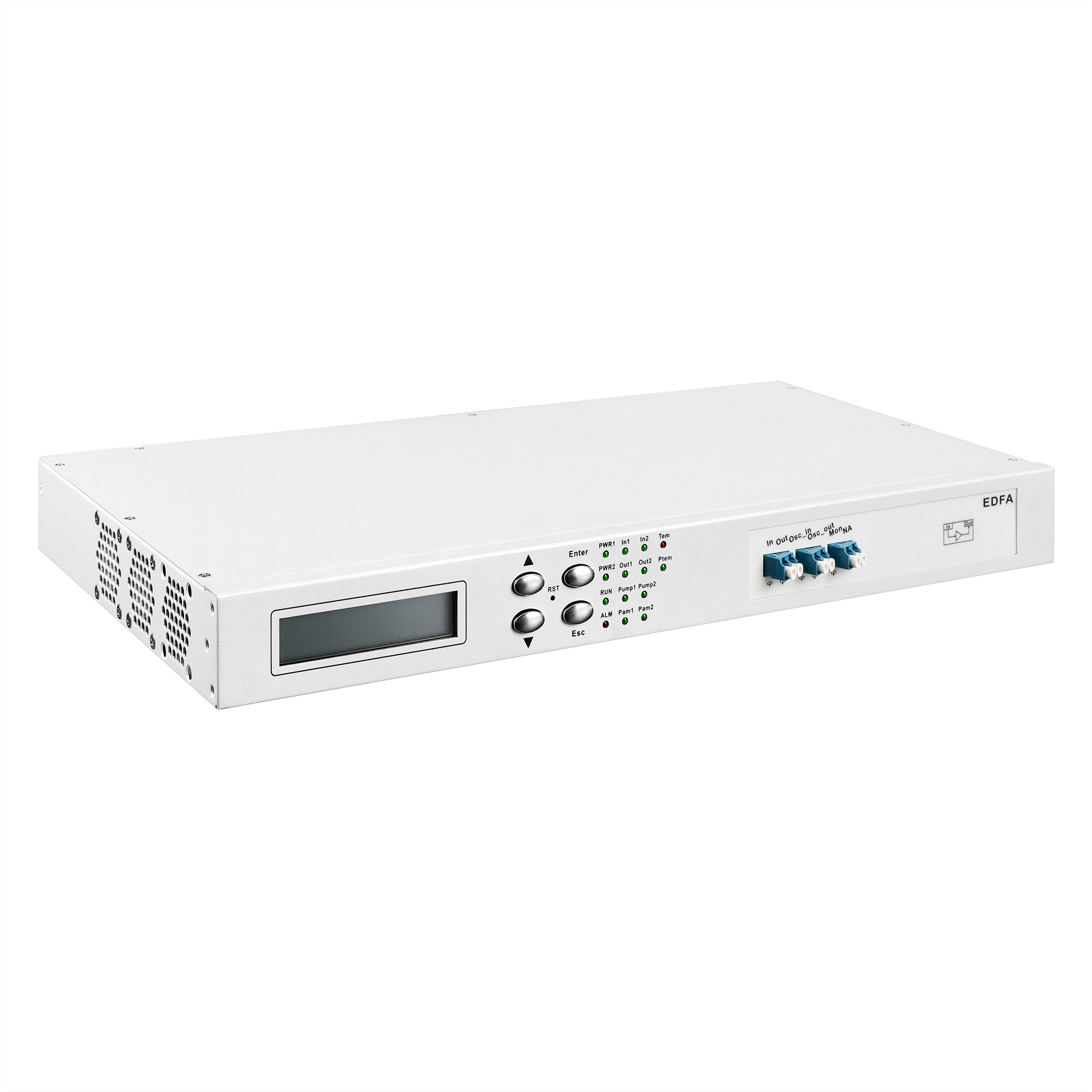
EDFA Rack-Mount / 1U Chassis-Based
The main function of EDFA(Erbium Doped Fiber Amplifier) optical amplification equipment is to compensate the power of signal light in the transmission link, and can simultaneously amplify the optical signals of up to 48 channels (channel interval is 100GHz) or 96 channels (channel interval is 50GHz) in C- band. It has the characteristics of flat gain, adjustable gain and small noise index, it is an indispensable part of DWDM system and future high-speed system, all-optical network long-distance transmission.
Description
Product Features
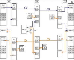
Application
Product Specifications
EDFA Device Interface Definition
Single Disk Monitoring Information & Device Settings