FSW-1X10-U
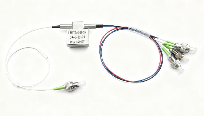
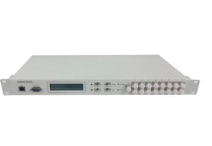
The FSW-1X10-U is a compact, rack-mounted optical switch designed for reliable and flexible light path routing in multimode optical systems. It supports one input and ten output channels, operating in the visible wavelength range of 350–600 nm with low insertion loss (≤1.5 dB) and high channel isolation (≥60 dB). Compatible with 50/125 μm or 62.5/125 μm multimode fibers and FC/PC connectors, it offers intuitive control via an LCD panel, RS-232, or Ethernet interface. Ideal for optical monitoring, test automation, and multi-point sensing applications, this 1U unit ensures stable performance across a broad operating temperature range and supports both manual and programmable switching modes.
Description
Product Overview
The FSW-1X10-U rack-mounted optical switch is an optical path control device. It can control the switching of optical fiber paths manually, locally, or remotely through buttons, serial communication, and Ethernet communication. It plays an important role in optical communication applications. The optical switch is mainly used for:
Product Features
- Low insertion loss and fast switching speed.
- Internal circuit self-test of the optical switch, with fault alarm notification.
- The serial port adopts the industrial-grade FT-232 USB-to-RS-232 chip.
- Equipped with an LCD display for intuitive visualization of optical path status, facilitating user operation.
- Optical path switching can be controlled via buttons, serial port commands, or Ethernet port commands. Button operations can be locked via serial port commands.
Performance Specifications
| Parameter Name | Specification |
| Model | FSW-1X10-U |
| Operating Wavelength | 350~600nm |
| Insertion Loss | ≤1.5 dB |
| Repeatability | ≤0.05 dB |
| Return Loss | ≥30 dB |
| Crosstalk | ≥60 dB |
| Wavelength-Dependent Loss | ≤0.25 dB |
| Polarization-Dependent Loss | ≤0.05 dB |
| Fiber Type | 50/125μm or 62.5/125μm |
| Connector Type | FC/PC |
| Monitoring Ports | RJ45, RS-232 |
| Operating Power Supply | AC: 100~240V |
| Operating Temperature | -10 ~ +60℃ |
| Storage Temperature | -40℃ ~ +85℃ |
| Chassis Type | 19-inch standard 1U rack (483 × 230 × 45 mm) |
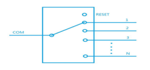
Optical Path Diagram
User Instructions
Panel Description
Front Panel
| Component | Description |
| POWER | Device power on/off button. |
| RJ45 | 10/100M Ethernet communication interface. |
| RS-232 | USB-to-RS-232 communication interface. |
| LCD Display | Shows device address, current channel, and related information. |
| Control Buttons | ▲ (up), ▼ (down), Enter (confirm), Esc (cancel). |
| Optical Interfaces | – COM: Input port (bidirectional support); – 1~16: Output ports (bidirectional support). |
Rear Panel
| Component | Description |
| AC Power Interface | Power input interface for the device. |
| Ground Terminal | Terminal for device grounding connection. |
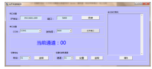
Communication Software Connection Instructions
(1) Serial Port Setting for PC
The serial port settings of the computer must match those of the device (default: 9600 baud rate, 8 data bits, 1 stop bit, no parity check). After connecting the device to the upper computer via the serial port, send commands via the upper computer software. The device will return data, allowing monitoring of the device status.
(2) Ethernet Port Connection
The device’s RJ45 Ethernet port supports two protocols: TCP Server and UDP. When selecting TCP/IP communication in the upper computer software:
- Set the protocol type to “TCP Client”;
- Enter the device’s IP address and port to establish a connection.Note: The IP address of the upper computer (computer) must be in the same subnet as the device’s IP address.