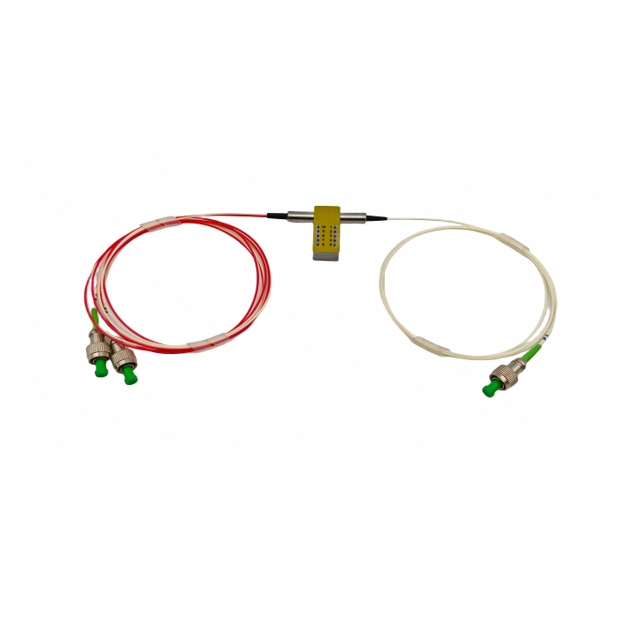
MFSW-1X2 optical switch type single mode optical switch module
The MFSW-1X2 is a compact, single-mode MEMS optical switch module designed for reliable and low-loss light path switching. It features low insertion loss (≤1.0 dB), high channel isolation (≥50 dB), and fast switching time (≤30 ms), making it suitable for a wide operating wavelength range from 1260 nm to 1650 nm. With dual control interfaces (UART and parallel TTL) and a durable design supporting over 10 billion cycles, this module is ideal for use in optical monitoring systems, LANs, multi-point sensing, and automated test equipment. It operates on a single 5V DC supply and is offered with FC/PC connectors for easy integration.
Description
Application
The MFSW-1×2 optical switch is a single-mode optical switch module with optical path switching functionality, mainly used in the following scenarios:
- Multi-channel optical monitoring in optical transmission systems
- Automatic switching of multi-light sources/detectors in LANs and multi-point dynamic monitoring systems for optical sensors
- Testing of optical fibers, optical components, networks, and field engineering optical cables in optical testing systems
- Assembly and adjustment of optical components
Product Features
- Low insertion loss and high reliability
- Simple control via parallel or serial interface
- Modular design
Product Performance
| Parameter | Specification |
|---|---|
| Operating Wavelength | 1260~1650nm |
| Test Wavelength | 1310/1550nm |
| Fiber Type | Single mode (9/125μm) |
| Connector Type | FC/PC |
| Fiber Length | 500±50mm |
| Insertion Loss | ≤1.0dB |
| Return Loss | ≥50dB |
| Polarization-Dependent Loss (PDL) | ≤0.15dB |
| Wavelength-Dependent Loss (WDL) | ≤0.3dB |
| Temperature-Dependent Loss | ≤0.3dB |
| Repeatability | ≤±0.1dB |
| Channel Crosstalk | ≥50dB |
| Switching Time | ≤30ms |
| Maximum Optical Power Handling | ≤500mW |
| Durability | ≥10⁹ operations |
| Operating Temperature | -5~+70℃ |
| Storage Temperature | -40~+85℃ |
| Power Supply | DC 5V ±5% |
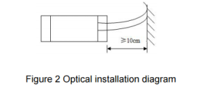
Appearance and Installation
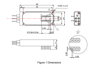
When installing the optical switch module, do not bend the optical fiber excessively (see Figure 2) to avoid affecting the performance of the module.
Pin Configuration
Digital Interface Electrical Specifications
| Item | Electrical Interface | Specification |
|---|---|---|
| 1 | Supply Voltage | 5V ±5% |
| 2 | Power Consumption | <500mW |
| 3 | Electrical Control Method | UART or Parallel mode (TTL level) |
Digital Interface Pin Assignment
| PIN # | NAME | DESCRIPTION |
|---|---|---|
| 1 | NC | No physical internal connection |
| 2 | VCC | Power Supply (5V) |
| 3 | STROBE | Falling Edge Active (input) |
| 4 | GND | Signal Ground |
| 5 | D0 | Data 0 (input) |
| 6 | D1 | Data 1 (input) |
| 7 | D2 | Data 2 (input) |
| 8 | D3 | Data 3 (input) |
| 9 | UART TX | UART Transmit (output) |
| 10 | UART RX | UART Receive (input) |
| 11 | GND | Case Ground |
| 12 | RDY | Ready (output, used for internal debugging) |
| 13 | MODE | 0=TTL mode, 1=UART mode (input) |
| 14 | RESET | 0=Reset (input) |
Notes
- The digital interface uses LVTTL level.
- Input control signal threshold level:
- Input logic high: Minimum 2V
- Input logic low: Maximum 0.8V
- All unused input pins must be held at logic high or connected to GND to ensure proper device operation.