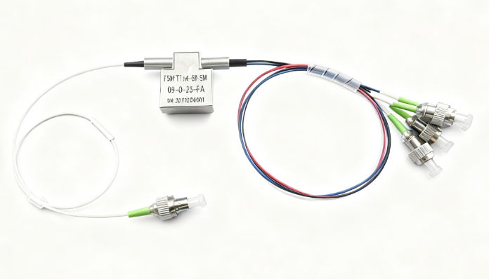
PM 1×3/1×4 Optical Switch
This Polarization-Maintaining (PM) 1×3 / 1×4 Optical Switch provides low insertion loss, high extinction ratio, and excellent channel isolation for reliable optical path switching in polarization-sensitive systems. Designed for operation at standard wavelengths including 1310 nm and 1550 nm, as well as 780 nm, 850 nm, 980 nm, and 1060 nm, it supports both latching and non-latching operation modes with high repeatability and long-term reliability.
Ideal for fiber lasers, communication systems, test instruments, and sensing applications, the switch complies with Telcordia GR-1209/1221 and RoHS standards, ensuring consistent performance under varying environmental conditions. Its compact design and flexible configuration options—including wavelength, fiber type, connector style, and operating voltage—enable seamless integration into diverse optical systems.
Description
Product Features & Applications
| Features | Applications |
| Low insertion loss | Fiber Laser |
| High extinction ratio | Fiber Sensor |
| High crosstalk | Communication System |
| Excellent environmental stability and reliability | Test Instrumentations |
| Polarization maintaining optical system |
Compliance
- Telcordia GR-1209-CORE
- Telcordia GR-1221-CORE
- RoHS
Performance Specifications
| Parameter | Value | |
| Type | 1X3or1X4 | |
| Wavelength (nm) | 1310 or 1550 | 780/850/980/1060 |
| Insertion Loss(dB) | ≤1.0(Typ 0.8) | ≤1.8(Typ 1.3) |
| Cross Talk(dB) | ≥55 | ≥55 |
| Return Loss(dB) | ≥50 | ≥50 |
| Extinction Ratio (dB) | ≥18 | ≥16 |
| Repeatability(dB) | ≤±0.05 | |
| Switch Time (ms) | 10 | |
| Lifetime (cycle) | >1,000,000 | |
| Switch mode | Latching or Non-latching | |
| Storage Temperature (°C) | -40 ~ +85 | |
| Drive Voltage (V) | 5 ±0.5 DC or 5V Pulse or 3V | |
| Work Current (mA) | <50 | |
| Fiber Type | See order information | |
| Dimension (LxMxH) (mm) | (L)23×(W)27×(H)8.5 | |
| (L)27.0×(W)12.6×(H)8.0 | ||
* The specifications are w/o connector.
* For devices with connectors, 0.3dB higher for IL, 5dB lower for RL and 2dB lower for ER.
* For device with connector, key aligned to slow axis.
Pin Configurations:
Latching Type:
| Type | Optical Route | Relay | Electric Drive | State Sensor | ||||||
| T1×4 | Pin 1 | Pin 5 | Pin 6 | Pin 10 | Pin 2‐3 | Pin 3‐4 | Pin 7‐8 | Pin 8‐9 | ||
| Latching | Input‐ Port 1(Black) | Relay1 | ‐‐ | ‐‐ | GND | V+ | Close | Open | Open | Close |
| Relay2 | V+ | GND | ‐‐ | ‐‐ | Open | Close | Close | Open | ||
| Input‐ Port 2 (red) | Relay1 | V+ | GND | ‐‐ | ‐‐ | Open | Close | Close | Open | |
| Relay2 | ‐‐ | ‐‐ | GND | V+ | Close | Open | Open | Close | ||
| Input‐ Port 3(blue) | Relay1 | ‐‐ | ‐‐ | GND | V+ | Close | Open | Open | Close | |
| Relay2 | ‐‐ | ‐‐ | GND | V+ | Close | Open | Open | Close | ||
| Input‐ Port 4(White) | Relay1 | V+ | GND | ‐‐ | ‐‐ | Open | Close | Close | Open | |
| Relay2 | V+ | GND | ‐‐ | ‐‐ | Open | Close | Close | Open | ||
Non-Latching Type:
| Type | Optical Route | Relay | Electric Drive | State Sensor | ||||||
| T1×4 | Pin 1 | Pin 5 | Pin 6 | Pin 10 | Pin 2‐3 | Pin 3‐4 | Pin 7‐8 | Pin 8‐9 | ||
| Non-Latching | Input‐ Port 1(Black) | Relay1 | ‐‐ | ‐‐ | ‐‐ | ‐‐ | Close | Open | Open | Close |
| Relay2 | V+ | ‐‐ | ‐‐ | GND | Open | Close | Close | Open | ||
| Input‐ Port 2 (red) | Relay1 | V+ | ‐‐ | ‐‐ | GND | Open | Close | Close | Open | |
| Relay2 | ‐‐ | ‐‐ | ‐‐ | ‐‐ | Close | Open | Open | Close | ||
| Input‐ Port 3(blue) | Relay1 | ‐‐ | ‐‐ | ‐‐ | ‐‐ | Close | Open | Open | Close | |
| Relay2 | ‐‐ | ‐‐ | ‐‐ | ‐‐ | Close | Open | Open | Close | ||
| Input‐ Port 4(White) | Relay1 | V+ | ‐‐ | ‐‐ | GND | Open | Close | Close | Open | |
| Relay2 | V+ | ‐‐ | ‐‐ | GND | Open | Close | Close | Open | ||
Mechanical Dimensions (Unit:mm)

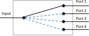
Optical Route
Ordering Information
| Type | Wavelength | Switch Type | Voltage | Fiber Type | Package | Fiber Length | Connector |
| PMS-1X4 | 1060=06 | Latching=1 Non-latching | 3V=3 | SM28=1 | Bare fiber=1 | 0.25m=1 | None=1 |
| C+L=2 | MINI Latching=3 | 5V=5 | 50/125=5 | 900um tube=3 | 0.5m=2 | FC/PC=2 | |
| 1310=3 | MINI Non-latching=4 | Special=0 | 62.5/125=6 | Special=0 | 1.0m=3 | FC/APC=3 | |
| 1410=4 | Special=0 | Special=0 | Special=0 | SC/PC=4 | |||
| Special=0 | SC/APC=5 | ||||||
| ST/PC=6 | |||||||
| LC/PC=7 | |||||||
| Duplex LC=8 | |||||||
| Special=0 |