
10G CWDM XFP Transceiver Supplier: Specify the Spare for an XFP Slot
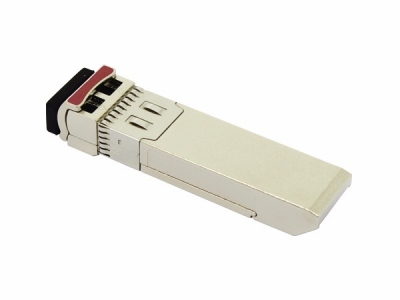
An older transport card may carry a 10G optical service through an XFP slot while newer equipment nearby uses SFP+. A maintenance buyer selecting a 10G CWDM XFP transceiver supplier should preserve the installed XFP interface, exact service rate and CWDM route before choosing a spare. Feiyi’s 10G CWDM XFP transceiver describes a hot-pluggable XFP footprint, a 9.95–11.3 Gb/s rate range and line-side/XFI loopback. Start there for XFP equipment; first confirm the card’s supported module configuration and the channel it already uses.
This is a replacement problem with two boundaries: the connection to the line card and the connection to the fiber network. The spare has to satisfy both. A newer module carrying a familiar wavelength or a longer distance label does not solve a mismatch at the cage, electrical interface or supported service.
Preserve the XFP interface before comparing 10G optics
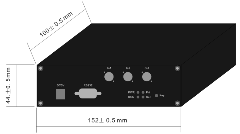
The Feiyi product is presented as an XFP-family optic; its catalog uses the name “XFP+.” For the equipment decision, preserve the documented XFP footprint and interface requirements. Do not interpret that naming as a statement that the module fits an SFP+ cage. Obtain confirmation against the installed card and its technical requirements.
9.95–11.3 Gb/s covers a family range, not automatic host negotiation
The listed rate range provides an initial screen for a 10G-class application. The page also names Ethernet, Fibre Channel and SONET/SDH applications. Those statements do not establish that an individual host automatically supports every listed service or every rate in the range. Identify the exact application used on the card and qualify the selected module in that operating mode.
A transport maintenance team replacing a module on an existing service should recover the card configuration as well as the optic label. If the service runs a particular line rate, record that rate rather than shortening the purchase description to “10G XFP.” The optical spare needs to operate in the application that must be restored, not merely in a different 10G laboratory test.
The +3.3 V and +1.8 V entries belong to the XFP host review
Feiyi lists +3.3 V and +1.8 V power supplies and states that no reference clock is required. Verify the complete interface requirements against the card, including any operating limits needed for qualification. These catalog features do not supply a named compatibility list or permission to modify an existing host power arrangement.
For an equipment developer, the sample approval should identify the host interface document and the conditions under which the module was evaluated. A maintenance buyer can instead use the approved spare configuration for the installed card. In either case, an optical continuity test alone cannot establish the electrical-interface result.
The Cisco 10G SFP+ module documentation discusses optical interoperability across module families while distinguishing their physical formats. Optical interoperability is therefore a separate question from fitting the host slot; Cisco platform statements do not approve a Feiyi XFP for a particular card.
Ask a 10G CWDM XFP transceiver supplier to resolve the exact ordering row
The Feiyi XFP ordering table lists XKXFC-XX96-10BD with a 40 km distance column, 1470–1610 nm CWDM wavelengths, EML/APD and LC/PC. It lists XKXFC-XX96-40BD with a 10 km distance column, 1270–1330 nm, DFB/APD and LC/PC. The suffixes do not align with a simple interpretation of the distance columns. Do not decode the suffix as a guaranteed reach.
Obtain a configured specification that reconciles the part identifier, selected wavelength, distance category and transmitter/receiver arrangement. The published rows can start the discussion, but they should not be silently corrected in the buyer’s order. The document approved by engineering needs to identify what the supplier will actually deliver.
The installed CWDM filter decides which wavelength the spare must use
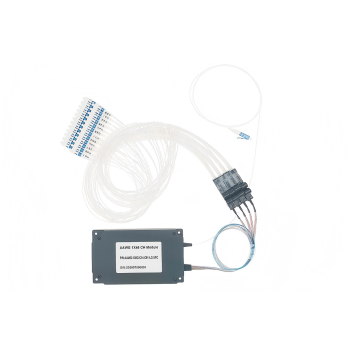
Feiyi’s 8-channel CWDM mux/demux is a relevant passive assembly when several services share a fiber route. Use the installed assembly’s channel schedule to identify the replacement wavelength. Channel count alone does not identify its occupied ports or the direction of the service being restored.
An integrator replacing a module in a partially populated system may see spare filter ports next to the affected circuit. A wavelength that fits one of those spare ports does not necessarily restore the original service. Keep the existing port assignment unless a deliberate network change is also approved. The far-end configuration and connection labels must agree with that decision.
Where the circuit uses different transmit directions or individual passive filters, recover the full directional map. One local wavelength label may describe only the outgoing path. A spare approval should identify the remote receiving relationship as well as the local transmission route.
Recreate the XFP optical budget with the supplied receiver limits
The product’s distance columns do not supply a complete transmitter-output, receiver-sensitivity or receiver-overload specification. Request those values for the exact selected channel and configuration. A link length is only one input to the optical review; filters, connectors and splices contribute loss, while the receiving limit establishes whether the delivered power is acceptable.
For a replacement on a long circuit, compare the new module’s optical limits with the existing approved budget. Do not assume the old calculation remains valid because the spare has the same distance category. If the supplied receiver differs from the previously approved configuration, the required input range may change.
For a temporary short laboratory connection, also check the receiver’s maximum permitted input. A module intended for a filtered outside-plant path may see a different power condition when directly connected on a bench. Define any required attenuation from the configured limits and measurement, rather than prescribing it from the family name.
The LC/PC entry belongs in the replacement’s patching record. Confirm the mating connector arrangement and polish. A change of connector or adapter can add loss and reflection that were not present in the original qualification. Keep the intended cord with the sample test rather than qualifying one arrangement and deploying another.
Separate XFI loopback from the line-side restoration test
Feiyi lists line-side and XFI loopback support. Determine how the installed equipment enables and reports those modes. A loopback result is meaningful only when its location in the signal path is known. It can help isolate part of an equipment problem, but does not automatically establish that the external CWDM route and far-end receiver are working.
Plan two observations. First, use the host’s approved diagnostic procedure to examine the applicable internal path. Then restore the normal mode and test the actual service through the intended passive route. Record which observation each result represents.
Suppose a technician obtains a satisfactory internal loopback result but the service fails after the external fibers are connected. The next review should include channel assignment, transmit/receive direction and the passive filter path. Replacing the optic again without preserving those identities may repeat the same fault condition.
The page describes diagnostic monitoring of module temperature and includes a DDM Y/N ordering field. Confirm the diagnostics provided by the selected version and their availability through the host. Do not expand a temperature-monitoring description into an unsupported promise about every optical diagnostic reading.
Retain a sample record that states the host, service mode, loopback mode and normal-path test conditions. This is more useful to a maintenance team than an unqualified “tested” label, particularly when a spare moves between equipment generations.
A replacement test should also preserve the physical fiber direction. Label the connections removed from the original XFP and identify the corresponding transmit and receive paths in the approved assembly. If a technician connects the spare through a temporary patch panel, record that change. The test result should not later be interpreted as verification of a different installed cord or connection route.
The selected module’s wavelength is particularly important when a maintenance kit contains several visually similar XFP units. The same family housing does not identify the channel. Keep the supplier configuration label readable after unpacking, and separate channels in the receiving record before the technician takes them to the equipment room. This avoids using insertion into a live card as the first identification step.
For acceptance measurements, agree whether the stated limits include the module’s connector and the external test cord. Use the same interpretation when comparing the sample with the delivered spare. If one result includes an extra adapter and another does not, their difference cannot be assigned entirely to the optic. Recording the reference planes makes the replacement review reproducible without claiming a test result that the catalog never supplied.
SFP+ and lower-rate CWDM options belong to different spare pools
The 10G CWDM SFP+ transceiver is relevant when the installed equipment requires SFP+. A similar optical channel may allow it to participate in a network design with an XFP endpoint, subject to approval of the two optical interfaces. It remains a different physical spare for a different host format.
The 1.25G/2.5G CWDM SFP family belongs to lower-rate equipment. A distributor maintaining mixed-generation stock should separate XFP, 10G SFP+ and lower-rate SFP records even when they share a CWDM wavelength. Rate, format and approved host application should be visible alongside the channel.
For broader context, Feiyi’s optical transceiver explanation describes the module’s place in a link. The maintenance decision here is narrower: preserve the interface and optical service that the installed XFP card requires.
Ship an identifiable XFP configuration that the technician can install
The family lists commercial and industrial temperature options. Select the option appropriate to the module’s actual case conditions and the host approval, then retain that identity with the order. An industrial label should not be treated as a general certification for every enclosure, vibration or humidity condition encountered in the equipment.
Agree protection for the optical interface and clear configuration labels through shipment and storage. The receiving documents should reconcile the selected wavelength and the approved ordering row, including the distance-column discrepancy where relevant. Do not rely on a photograph of the common housing to distinguish different CWDM configurations.
Confirm availability and dispatch timing for the actual approved spare. The website does not establish inventory or a guaranteed replacement-delivery period. If a different module is proposed to accelerate delivery, return the changed interface and optical limits to engineering before accepting it as equivalent.
Keep the XFP slot, selected channel and service mode on the same replacement record. Once the suffix ambiguity has been reconciled and the normal-path test passes under the approved optical conditions, the buyer has a defensible spare configuration. Until then, choosing the more convenient part number risks restoring the wrong interface or the wrong wavelength.