Choose the Passband Profile With an Athermal AWG Supplier Before Approving Center Loss
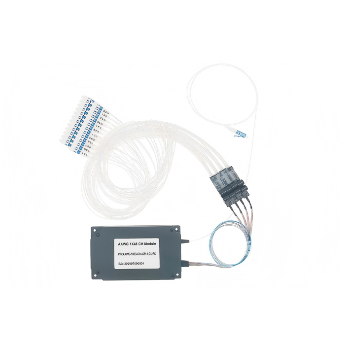
The lowest loss at a channel center may be the wrong priority when the transmitter’s usable spectrum moves away from that center. Choose an athermal AWG supplier by the optical interval your system must transmit, then compare the corresponding loss profile. Feiyi’s 40/48-channel AWG module distinguishes flat-top and Gaussian options, making it a useful starting point for that decision. Confirm the source interval, channel plan and applicable environmental limits before approving a center-loss figure.
For a network engineer or equipment buyer, the array must transmit the required channels under the actual source and installation conditions. The word athermal identifies a temperature-compensated design approach; it should not be interpreted as infinite spectral stability or immunity to the transmitter’s own wavelength change.
An athermal AWG supplier should begin with the transmitter’s accepted interval
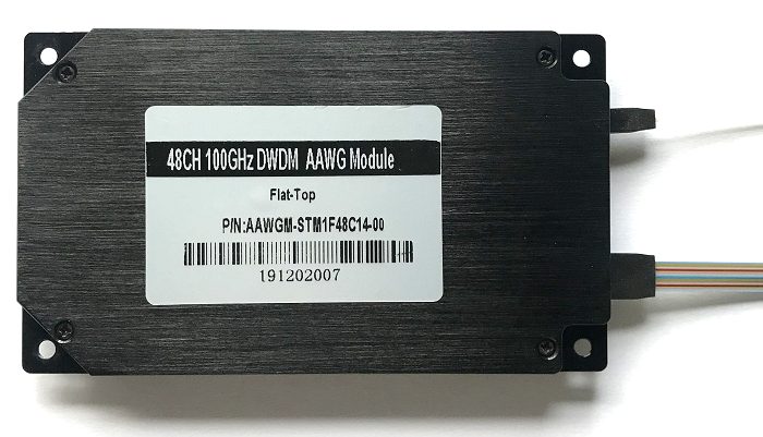
Feiyi’s 40/48-channel module lists 100 GHz spacing, C-band operation and a 48-channel selection identified as C13–C60 or customized. It gives ±0.10 nm channel passband and ±0.06 nm wavelength accuracy entries. These are distinct from the width at a specified loss threshold. Match the required source interval to the confirmed response of the ordered profile.
A source held close to its nominal center may place a high value on center loss. A source requiring a wider usable interval may place more value on a flatter response. Neither preference can be settled by channel count alone. The engineer should identify the allowed source detuning and spectral occupation before deciding which catalog loss condition is relevant.
The Gaussian center-loss advantage does not describe the whole passband
The Gaussian column lists insertion loss at the ITU center of 2.0 dB typical and 3.0 dB maximum. Across the passband, it lists 3.2 dB typical and 4.5 dB maximum. A buyer should not budget the 3.0 dB center maximum for a condition that actually requires the full passband limit.
The flat-top column lists center loss of 4.2 dB typical and 5.0 dB maximum, with passband loss of 4.5 dB typical and 5.5 dB maximum. Its profile trades different transmission behavior against the center-loss figure. The appropriate comparison is the loss at the interval the source needs, using the same reference condition for both alternatives.
Flat-top and Gaussian AWG bandwidths should retain their loss threshold
The same module lists 1 dB bandwidths of 0.38 nm for flat-top and 0.20 nm for Gaussian, with 3 dB bandwidths of 0.58 and 0.38 nm respectively. A bandwidth value without its threshold is incomplete. A broader 3 dB width does not mean the full interval meets a stricter 1 dB condition.
| Transmission condition | Flat-top column | Gaussian column |
|---|---|---|
| Maximum loss at ITU center | 5.0 dB | 3.0 dB |
| Maximum loss across passband | 5.5 dB | 4.5 dB |
| Bandwidth at 1 dB | 0.38 nm | 0.20 nm |
| Bandwidth at 3 dB | 0.58 nm | 0.38 nm |
These entries are comparison conditions for the named module, not measured curves from a supplied sample. The product notes that its insertion losses include connectors. Preserve that boundary in the system calculation; do not automatically add a second generic connector allowance to the same supplied interfaces.
Cascaded AWG filters should be assessed over the required source spectrum
Consider a link with multiplexing at one end and demultiplexing at the other. Both responses act on the same transmitted spectrum. Adding two center-loss numbers does not establish performance away from the center. Evaluate the combined route over the source interval, particularly if intermediate filtering is also present.
A broader flat-top selection can be relevant when spectral occupation or drift makes the usable interval consequential. A Gaussian selection can be relevant when the approved source stays within a narrower interval and center loss dominates the decision. Neither profile name establishes a data rate or modulation-format approval without the system-specific assessment.
NTT Innovative Devices’ 100 GHz AWG documentation explains the distinction between center-focused and wider transmission approaches. Its 50 GHz athermal overview illustrates the general temperature-compensated array function. Their specifications and qualification statements are not acceptance limits or certifications for Feiyi.
A 48-channel AWG order needs an approved frequency-to-output list
Feiyi’s separate 48-channel 100 GHz athermal AWG lists a physical module of 80 × 40 × 9 mm, with input-fiber length of 900 mm and output-fiber length of 1000 mm. It presents 40/48-channel selections and a channel plan. Confirm the actual output count and plan for the chosen assembly rather than combining different family’s dimensions or channels.
A corrected AWG channel list is more useful than a copied label sequence
The published frequency and wavelength listing contains inconsistent entries, so a purchasing team should request an approved complete plan before assigning output connections. Keep nominal frequency, derived wavelength and physical port identity in the same record. Do not assume that a printed row number is the ITU channel number or that a repeated wavelength identifies two different valid channels.
The 48-channel listing also has a passband-ripple row whose unit needs clarification. Do not turn it into an acceptance figure without confirmation. Other clearly identified entries, such as the 100 GHz spacing and the stated module envelope, can inform initial selection while the disputed rows are resolved for the order.
O-band 150 GHz and C-band 50 GHz arrays address different spectral plans
The 17-channel 150 GHz athermal AWG is an O-band product with a frequency plan spanning 233.6 to 231.2 THz. It lists a 100 × 80 × 9 mm module and seventeen outputs. This is not a smaller-port substitute for a C-band 100 GHz array. The wavelengths and source plan differ fundamentally.
The 96-channel 50 GHz athermal AWG describes a denser C-band arrangement. Its mechanical information identifies SMF-28e common fiber in 900 µm tube and ribbon channel fibers, with a 120 × 70 × 10.5 mm envelope. The page contains a copied O-band channel table that should not be used to define this 96-channel order.
The 96-channel ribbon interface requires confirmed channel identification
A high-count array places more significance on the relationship between ribbon identification and channel position. Request the complete approved mapping and the actual supplied terminations. A ribbon color sequence helps identify physical fibers but does not independently establish their optical frequencies. Preserve both identities before the integrator terminates or routes them.
Do not transfer the 17-channel O-band loss and environment to the 96-channel C-band family. The 96-channel listing includes contradictory or ambiguous optical entries that need an approved revision. Its count, spacing and mechanical route can establish which family is being considered; disputed figures should remain outside a release specification until resolved.
Athermal operation still needs an installation temperature boundary
The 40/48-channel comparison module lists operation from −5 to +65 °C, maximum input power of 500 mW, SMF-28e or customized fiber and LC/APC. These are specific limits and interfaces for that family. They should not be widened by borrowing another AWG’s environmental table or a competitor’s no-control statement.
For an enclosure exposed to thermal variation, identify the temperature at the installed array and the transmitter’s behavior under the same operating conditions. Compensation in the array does not keep the transmitter’s center fixed. Both must stay within the agreed optical relationship for the source interval to remain usable.
The 40-channel 100 GHz listing needs a clarified bandwidth revision
Feiyi’s 40-channel 100 GHz athermal AWG is another real catalog family. Its generic bandwidth and several dimensional or power rows need clarification. In particular, the listed 1 dB and 3 dB widths do not form a consistent increasing-width sequence for the same response. Request the approved profile and spectral curve instead of choosing the favorable row.
A qualification statement in a listing should also be accompanied by applicable documentation if the purchase requires formal evidence. No independently authenticated test certificate is provided here. State the actual contractual qualification requirement and confirm the supplied model’s evidence rather than repeating a label as an unrestricted certification claim.
AWG acceptance should preserve the profile instead of averaging away its limits
Ask for results that identify each ordered channel and the agreed spectral condition. A mean loss across all outputs can conceal an unfavorable individual channel. A center reading can conceal a passband-edge condition. Establish both the individual-channel limits and the variation relevant to the completed link.
The comparison module lists maximum uniformity of 1.5 dB for both profiles and PDL of 0.5 dB maximum. Keep those conditions separate from absolute loss. If acceptance includes polarization variation, agree the input-state method; a fixed-state loss trace is not a complete PDL assessment. Likewise, channel uniformity should identify the wavelength reference being compared.
For a Gaussian sample, a sweep should establish the relevant off-center loss rather than stop at the nominal frequency. For a flat-top sample, the wider threshold bandwidth should still be tied to the agreed loss condition. Record how the wavelength reference was established and which connector interfaces are included. A plotted curve without those conditions can look convincing while answering a different source requirement.
The same comparison module lists ripple values of 0.2 dB typical and 0.5 dB maximum for flat-top, and 1.0 dB typical and 1.8 dB maximum for Gaussian. Treat ripple as its own spectral variation condition. It does not replace the maximum passband-loss limit, and it should not be added indiscriminately to a worst-case limit that already represents the relevant response. Agree the applicable interpretation for the selected profile.
When a design change reduces transmitter wavelength control, reopen the filter approval even if the nominal grid remains unchanged. The previously accepted narrow interval may no longer describe the source. A Gaussian module chosen for its lower center loss may still work, but that conclusion requires checking the wider needed interval. Switching to flat-top also requires reviewing its higher listed absolute loss against the receiver budget.
For a temperature-sensitive cabinet, request the evidence needed to demonstrate the selected module’s behavior across the required environment, using the relevant channel and spectral condition. A single ambient sweep does not independently prove temperature performance. The buyer should distinguish a request for those actual results from a hypothetical acceptance method; no Feiyi environmental experiment is claimed here.
For an OEM receiving a multi-output module, preserve the common-fiber identity and protect the approved output terminations while the leads are separated for integration. Mounting should follow the chosen package drawing rather than the envelope of another AWG family. Request packing that avoids loading the common exit or ribbon interface; no standard factory packing method is assumed.
Feiyi’s Gaussian and flat-top AWG discussion gives further technical context. Release the array order from a confirmed profile, source interval and channel plan. If only the center-loss number has been approved, the buying decision still lacks the condition that determines how the installed transmitter will actually pass through the array.