A Custom Fiber Optic Components Manufacturer Needs the Test Conditions Behind a Sample Revision
Before requesting a second custom sample, identify where the first assembly stopped meeting the requirement. Changing the fiber, connector and optical tip together can make the next result difficult to interpret. A custom fiber optic components supplier needs a defined mismatch and the conditions under which it occurs. Feiyi’s custom PM patch cords, PM single-fiber pigtails and custom collimators give different revision routes. Start by distinguishing a connectorized loss issue, a polarization issue and a free-space coupling issue.
The examples here are hypothetical OEM and laboratory decisions, not reported Feiyi sample failures. Their purpose is to make a revision request specific enough to evaluate. The catalog’s customization fields identify options to discuss; they do not promise that every combination of targets can be manufactured.
A custom fiber optic components supplier should receive the measurement condition with the mismatch
A low delivered power reading can originate at several boundaries. A connectorized PM patch cord, an optical pigtail entering a device and a collimator launching into free space are not measured in the same way. Record the launch wavelength, input state, endpoints and the optical elements included before selecting which component to revise.
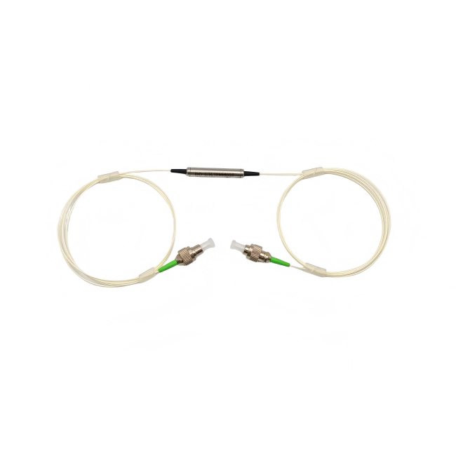
For the custom PM patch family, Feiyi lists APC and UPC grades with different loss and return-loss limits. APC P-grade insertion loss is no greater than 0.40 dB, while UPC P-grade is no greater than 0.30 dB under the listed conditions. These should not be used as universal installed-path limits without interpreting the specification’s connector note.
A connectorized PM sample needs an agreed assembly-loss boundary
The custom patch listing states specifications without connectors and gives a connector correction of 0.3 dB higher insertion loss, 5 dB lower return loss and 2 dB lower extinction ratio. Agree the actual delivered test boundary before interpreting an assembled result. A purchaser should not reject a connectorized assembly simply by comparing it with an unconnectorized device value.
If a sample’s loss changes when it is remated, investigate the reference connections and inspection condition first. The product lists repeatability no greater than 0.1 dB and interchangeability no greater than 0.2 dB, but those are separate conditions. A different mating counterpart can introduce a different comparison. Keep the counterpart and test reference identified when requesting a revision.
A request to change UPC to APC also changes the mating finish. Confirm the equipment interface at both ends before making that change. The supplier needs an approved compatible interface; a preference for a larger return-loss number does not establish that the revised connector will mate with the existing instrument.
A PM-axis mismatch should not trigger an unrelated package change
The patch family’s listed extinction ratio is at least 20 dB, with the default connector key aligned to the slow axis. If the receiving instrument expects another orientation, identify that requirement explicitly. A familiar shell and suitable wavelength do not confirm that the sample’s reference matches the instrument.
Consider an OEM whose transmitted power is acceptable but whose polarization-sensitive downstream measurement is inconsistent. Establish the input state and the reference expected by the receiving element. If the problem is an axis convention, changing the jacket diameter or housing length will not resolve it. Request the specific approved axis arrangement instead.
PM pigtail extinction belongs to the device’s actual termination
The custom PM single-fiber pigtail lists extinction ratio of at least 23, PM980/PM1550/PM1310 fiber choices and 1.8 × 6.5 or 1.0 × 6.5 mm structures. A pigtail installed in an optical device introduces a different mechanical and optical interface from a two-ended patch cord. Preserve the relationship between the PM axes and the receiving device’s physical reference.
The pigtail’s typical insertion-loss entries are 0.18 dB for P grade and 0.20 dB for A grade, with maximum entries of 0.21 and 0.25 dB. A revision should identify the supplied grade and how its performance is measured. Do not attach the patch cord’s connector correction automatically to the pigtail’s distinct device boundary.
The product gives a 500 mW maximum power-handling entry. This does not inherit the higher selectable power entries found in the collimator family. If the sample revision increases launched power, revisit the selected pigtail as well as the next optical element. Low power measured farther downstream does not establish the input condition at this component.
Custom collimator revisions should distinguish beam size from coupling efficiency
Feiyi’s custom PM collimator lists 1310/1550 nm and 980/1064 nm groups, with separate loss entries. The telecom group lists 0.20 dB typical and 0.25 dB maximum; the shorter-wavelength group lists 0.30 and 0.35 dB. Preserve the chosen wavelength and measurement arrangement when comparing a second sample.
The ordering information includes C-lens and G-lens routes and working-distance options. A working distance describes a target geometry, not a complete guarantee of coupled power into an arbitrary receiving element. Provide the destination and acceptable beam or coupling condition instead of asking only for a longer working distance.
A smaller collimated beam does not automatically improve the receiver result
The collimator lists a beam diameter below 0.5 mm, but a buyer should clarify the applicable definition and target plane for the selected assembly. A receiver has its own acceptance aperture and angular condition. A smaller spot at one plane can be accompanied by another condition that makes the final coupling worse.
For an instrument sample that works on a bench but loses power after mounting, compare the actual installed alignment and receiving plane with the approved setup. The mounting change may have altered the beam’s relation to the receiver. The supplier needs that geometry before a lens substitution can be meaningfully evaluated.
The collimator offers several power selections and package diameters. Those options should be confirmed as a specific supplied combination. Do not pick the smallest listed envelope and the largest listed power independently and assume they describe one available model. Ask for a drawing and approved optical specification for the chosen version.
A wedge-lensed fiber changes the coupling geometry rather than acting as a packaged collimator
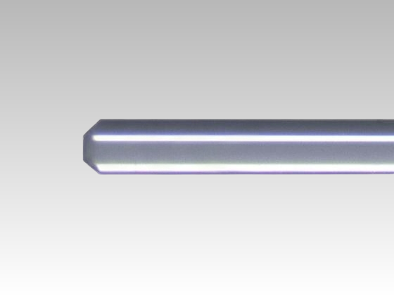
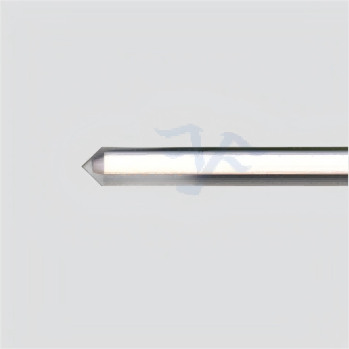
Feiyi’s wedge-lensed fiber lists SM, MM and PM material routes, tip radius from 8 to 12 µm and wedge angle from 60° to 120°. It identifies applicable coupling far-field divergence from 15° to 40°. Those are distinct geometric quantities; the wedge angle is not the same as the emitted or accepted divergence.

The wedge tip’s orientation should be preserved while one geometry is changed
A laser-module buyer comparing two tips should retain the relevant target plane and orientation while changing the agreed tip variable. Otherwise the difference can originate from mounting or orientation rather than the revised curvature. Provide the coupling target and the permitted geometry to the supplier before requesting a second tip.
The wedge listing allows customized fiber length and stripped coating length. Those are meaningful integration fields because the bare region and support location affect how the tip is installed. Specify the region needed by the mount without inventing a minimum bend radius or a process that the supplier has not approved.
The wedge description states that the tip is processed directly on bare fiber without auxiliary adhesives and that coating is applied to the fiber endface. A custom request should therefore identify the tip geometry and coating requirement rather than assume a separate glued lens assembly. If the receiving mount needs an adhesive elsewhere, that installation decision requires its own approval and should not be confused with the stated tip construction.
OZ Optics’ tapered and lensed fiber technical document explains the broader geometry-dependent coupling function. It supports distinguishing tip shape from a complete optical assembly. Another manufacturer’s tolerances and process claims should not be written into a Feiyi custom order.
A custom PM WDM sample should retain both wavelength routes during revision
Feiyi’s PM filter WDM lists paired channel and reflection wavelength selections. One listed combination associates the 1020–1080 nm channel with a 960–990 nm reflection range. Other combinations cover telecom and longer-wavelength routes. Confirm the actual selected pair and port drawing before modifying a wavelength requirement.
The pass and reflection insertion-loss entries are each no greater than 0.8 dB, with a minimum extinction entry of 18 and a 300 mW maximum power-handling entry. These belong to this family and the approved route. A sample revision intended to improve one branch should retain the requirements of the other branch rather than treat it as an unused consequence.
A WDM port mistake should be resolved before asking for a lower-loss filter
An OEM observing poor transmitted power at the expected output should first confirm that the launched wavelength is being measured on its intended pass or reflection route. A spectral routing mismatch can resemble high loss when the measurement uses the wrong port. Request the selected port map and verify the path before changing a loss target.
The filter’s PM-axis and wavelength requirements should be assessed separately. A correct wavelength route does not establish the output state needed by the next device. Conversely, an acceptable extinction result on one route does not verify the other wavelength’s insertion loss. Retain the actual branch and launch condition with each sample result.
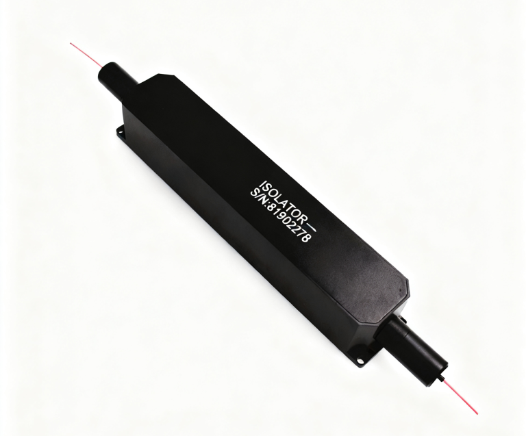
A sample change that increases combined launched power should identify the condition at the WDM common interface, as well as each individual source. The listed 300 mW entry is not evidence that a high-power collimator option automatically makes the complete combination suitable. Confirm the selected route and device approval before making a power change. This is especially important when the revision combines a new pump route with an existing signal path.
The PM WDM lists a 5.5 mm diameter by 38 mm package and operation from 0 to +75 °C. Its placement inside the revised module should remain compatible with those selected conditions. A longer patch lead can change the mounting arrangement without changing the filter’s own environmental limit; assess the temperature at the filter location rather than the remote test instrument.
The second custom sample should change only the agreed unresolved condition
Once the mismatch is localized, identify the revision that addresses it: connector finish or axis reference for a patch, termination geometry for a pigtail, receiving-plane relationship for a collimator, tip geometry for a wedge fiber or spectral route for a WDM. Keep the unaffected requirements stable enough to compare the new result with the first approved setup.
For delivery, request protection suited to the revised interface. A bare wedge tip needs protection of its exposed optical geometry; a connectorized PM cord needs protected faces and identifiable ends. Preserve the specific drawing revision with the sample. These are order requirements to agree, not claims of a standard packing method or guaranteed sample lead time.
Feiyi’s custom wavelength-routing discussion provides additional configuration context. Approve a second sample from a defined remaining problem and an unchanged measurement reference. If the supplier cannot tell which condition the revision must improve, the next sample can add another variation without answering the original engineering question.