PM Optical Isolator Manufacturer: Build a Source-Protection Matrix Across Wavelength and Power Classes
A buyer comparing a PM optical isolator manufacturer should look beyond one successful sample and ask whether the approved product family matches every source platform the company actually builds. Feiyi’s polarization-maintaining isolator range includes wavelength-specific products from 780 nm through 1950 nm, plus high-power variants around 980 and 1064 nm. That range matters because wavelength, isolation, forward loss, fiber type, power class, and package are connected decisions. A 1064 nm laboratory isolator is not automatically the same production item as a 1064 nm high-power isolator simply because both protect a laser from reverse light.
For an OEM or distributor, the practical task is to build a source-protection matrix: identify the wavelength platform, expected forward power, required reverse isolation, acceptable insertion loss, PM-axis convention, connector or bare-fiber interface, and package constraints for each instrument family. The manufacturer can then supply against an approved configuration instead of receiving a generic request for “PM isolator.”
A PM optical isolator manufacturer should be qualified across wavelength families, not one catalog line
Feiyi lists PM isolator products at 780, 850, 980, 1030, 1064, 1480, 1650, and 1950 nm, together with high-power 980 and 1064 nm devices. Those options support different lasers, amplifiers, test systems, and photonic assemblies. The buyer should keep the wavelength family visible in the internal part number because PM fiber and optical materials are selected around that operating region.
A 780 nm platform and a 1950 nm platform should never share a generic “PM isolator” stock code
The PM 780 nm Polarization Maintaining Fiber Isolator and the PM 1950 nm Polarization Maintaining Fiber Isolator solve the same broad function—suppressing reverse optical energy while maintaining the intended polarization—but they belong to very different wavelength platforms. A distributor or service department should therefore separate them by wavelength before considering connector or cable similarities.
For an OEM, the approved drawing should name the operating wavelength and fiber family rather than relying on a housing photograph. This makes it harder for a replacement program to install a mechanically familiar but optically incorrect device.
Wavelength is only the first filter; power class selects another isolator family
Feiyi publishes both a standard PM 1064 nm Fiber Optic Isolator and a PM 1064 nm High-Power Optical Isolator. The standard page lists maximum power handling of 300 mW. The high-power page lists maximum power handling of 2 W and a larger rectangular package. Those are different approved product classes, not a single component with an optional label.
The source-power plane should therefore be defined before the final part is selected. If the isolator sits after a stage where optical power has increased, the power seen by the device may differ substantially from an isolator located close to a seed source. The buyer should specify the installed location and power envelope without assuming that a standard low-power configuration can be moved downstream unchanged.

PM optical isolator manufacturer evaluation should compare forward loss with reverse protection
An isolator has two jobs that pull the design in different directions: allow the wanted forward signal through with acceptable loss, and suppress unwanted reverse light. Feiyi’s standard 1064 nm product makes this trade-off visible by publishing single- and dual-stage versions.
| Feiyi 1064 nm standard isolator | Single stage | Dual stage |
|---|---|---|
| Operating wavelength | 1064±5 nm | 1064±5 nm |
| Typical isolation | 35 dB | 52 dB |
| Minimum isolation | 28 dB | 45 dB |
| Typical insertion loss | 1.5 dB | 2.4 dB |
| Maximum insertion loss | 1.8 dB | 3.2 dB |
| Minimum extinction ratio at 23°C | 20 dB | 20 dB |
Dual stage should be justified by the reverse-light budget, not selected automatically
The dual-stage configuration publishes higher isolation, but it also has higher insertion loss. A laser designer should therefore estimate how much reverse power can reach the protected source and how much forward loss the system can tolerate. The answer may justify dual-stage isolation in one instrument and a single-stage part in another.
This choice should appear in the approved source-protection matrix. If purchasing later changes a dual-stage line to a single-stage part because the wavelength and connector match, the system can lose reverse isolation even though the replacement fits mechanically. Conversely, choosing dual stage everywhere can spend more forward optical budget than a project needs.
High-power 1064 nm data should not be copied onto the standard 1064 nm family
The high-power 1064 nm page publishes typical isolation of 35 dB for single stage and 50 dB for dual stage, minimum isolation of 27 dB and 45 dB, and typical insertion loss of 1.8 dB and 3.8 dB respectively. It lists a 2 W maximum power-handling value and package dimensions of 33 × 17 × 11.5 mm for single stage and 60 × 17 × 11.5 mm for dual stage.
Those figures differ from the standard 1064 nm device. A quality file should preserve the exact product page or approved specification used for the sample rather than treating every 1064 nm PM isolator as one interchangeable record.
Polarization alignment belongs in the manufacturing release for every PM isolator
Feiyi’s standard 1064 nm isolator specifies PM1060 fiber, slow-axis operation with fast-axis cutoff, and a minimum fiber length of 1 m at each end. The high-power 1064 nm product similarly describes slow-axis operation and fast-axis cutoff. These details tell the buyer how the isolator participates in the PM chain.
A connectorized isolator needs the same axis convention as its PM patch cord
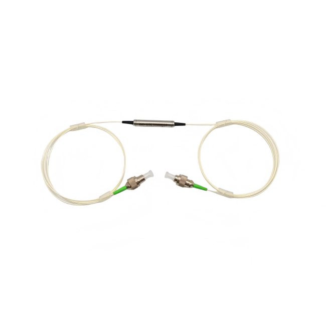
If the isolator is terminated with FC or SC connectors, the system drawing should define how the connector key relates to the PM axis and should match the adjacent PM patch cord. A correct isolator can still produce poor system polarization performance if the neighboring cable is keyed to a different convention or installed with an unintended orientation.
The PM Optical Isolator range should therefore be reviewed together with the project’s approved PM patch-cord interface. The isolator is not an isolated purchasing decision when the source chain depends on polarization continuity.
Bare-fiber builds move the axis-control responsibility into the assembly process
When the product is supplied with bare fiber rather than connectors, the assembly or splicing process must preserve the intended PM alignment. Receiving inspection should record how the test launch is aligned so that extinction-ratio measurements are comparable between lots. A bare-fiber sample that passes under an optimized laboratory alignment does not define the production splice process by itself.
For an OEM handoff, the isolator drawing and the splice or pigtail drawing should share the same axis terminology. That prevents manufacturing technicians from interpreting “slow axis” differently at the component and module levels.
A PM optical isolator manufacturer should support a two-direction acceptance test
Forward insertion loss and reverse isolation are different measurements and should both be represented in the acceptance plan. A useful incoming test first verifies the forward path at the specified wavelength and launch condition, then measures the reverse suppression under a defined setup. Return loss and extinction ratio can be checked according to the product family and project requirements.
Testing only forward throughput cannot prove source protection
A cable or isolator can transmit acceptable forward power while providing less reverse isolation than expected. If the purpose of the device is to protect a laser from reflections, a receiving test that checks only forward loss misses the central function. The manufacturer’s published isolation value should therefore be part of the approved specification.
Feiyi’s standard 1064 nm device also publishes return loss of 50 dB, PDL of 0.15 dB, operating temperature from -20 to +75°C, and storage from -40 to +85°C. These values create additional boundaries for the selected family, but they do not replace the system’s own back-reflection analysis.
Connector inspection should happen before optical acceptance
Dirty or damaged connector end faces can raise loss and reflection and make a good isolator appear defective. For connectorized deliveries, the receiving sequence should identify the product, inspect and clean end faces when needed, then perform the optical measurements. For bare-fiber versions, the buyer should document the launch or splice method used during acceptance.
Feiyi’s public isolator pages do not state one universal packaging method for every wavelength and power class. If an OEM needs specific connector protection, lead identification, or handling for a high-power rectangular package, those requirements should be attached to the exact order rather than assumed from another isolator family.
High-power PM isolators deserve their own mechanical and thermal review
Moving into a high-power isolator family changes more than one line in the optical table. Feiyi’s PM 980 nm High-Power Optical Isolator is published as a separate TGG-based product with a 980±5 nm operating wavelength and a 150 × 28 × 26 mm package. Its page lists typical isolation of 65 dB, minimum isolation of 50 dB, typical insertion loss of 0.8 dB, maximum insertion loss of 1.2 dB, and minimum extinction ratio of 20 dB. The page also publishes a broad high-power handling range rather than the hundreds-of-milliwatts figure shown on standard low-power products.
A larger high-power package changes the module integration plan
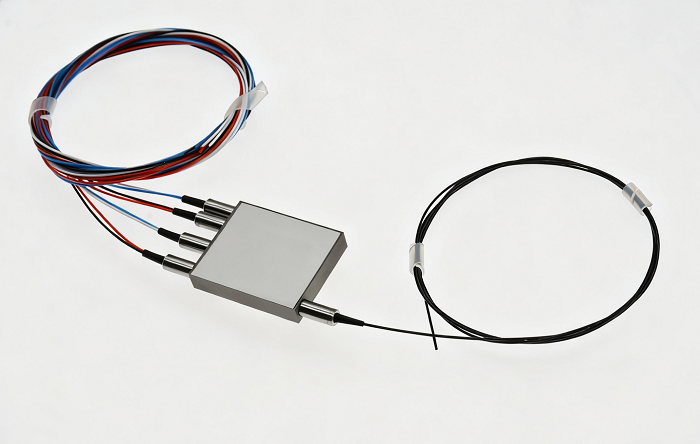
An OEM that previously mounted a cylindrical low-power isolator cannot assume that the high-power version will fit the same bracket, thermal environment, or fiber-routing path. The mechanical drawing should therefore be reviewed at the same time as the optical power requirement. If the isolator is placed close to a laser head, keep-out space, lead exit direction, connector access, and service removal can all influence the final assembly.
Feiyi lists MOPA fiber laser, fiber laser, PM fiber amplifier, and system-test uses on its high-power product pages. Those are useful application references, but the buyer should still calculate the power and reflection conditions of the exact installation. A “high-power” label is not a substitute for verifying that the chosen wavelength, isolation, loss, package, and stated power class match the real location in the optical chain.
For distributor inventory, high-power and standard isolators should also be separated even at the same nominal wavelength. A receiving label that includes the wavelength, stage count, power family, and package reference is more reliable than visual identification after the device has been removed from its original documentation.
Manufacturer qualification should preserve the product family that passed the sample stage
Feiyi’s earlier article Before Approving a PM Optical Isolator Supplier for a Laser Chain explains how an isolator fits a particular laser chain. The manufacturer-level decision adds another layer: the accepted sample must become a controlled product record that can survive repeat orders, service replacements, and multiple wavelength platforms.
For each approved isolator, keep the wavelength, standard or high-power family, single- or dual-stage construction, published isolation and insertion-loss limits, PM fiber, working axis, connector or bare-fiber interface, lead length, package, and power class together. If any of those fields changes, the revision should be visible to engineering and receiving rather than hidden behind the same generic stock description.
Build the source-protection matrix before consolidating PM isolator purchasing
Consolidating isolator purchasing can be useful for an OEM or distributor, but consolidation should happen at the manufacturer relationship level, not by collapsing different optical configurations into one part number. A 780 nm low-power isolator, a standard 1064 nm single-stage device, a high-power 1064 nm dual-stage device, and a 1950 nm isolator can come from the same manufacturer while remaining four distinct controlled products.
The strongest PM optical isolator manufacturer program is therefore easy to audit: each source platform has a defined wavelength, power plane, isolation requirement, forward-loss budget, PM-axis convention, and acceptance method. When that matrix exists, buyers can compare manufacturer capability without turning a successful laser-protection component into an unsafe substitution exercise.