1×8 Mechanical Optical Switch Supplier: Preserve Route State, Drive Logic and Port Map in a Replacement
1×8 Mechanical Optical Switch Supplier: Preserve Route State, Drive Logic and Port Map in a Replacement
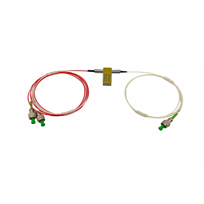
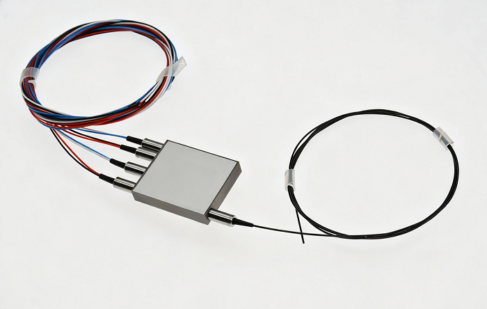
A 1×8 mechanical optical switch supplier should receive the electrical control logic and optical port map before a replacement is approved. Feiyi’s 1×8 Mechanical Optical Switch routes one common optical input to one of eight output fibers and supports both latching and non-latching control. The product page lists 3 V or 5 V operation, switching time of no more than 8 ms, repeatability within ±0.02 dB, durability of at least 10 million cycles and optical power up to 500 mW.
For a buyer maintaining laboratory routing, system monitoring, OADM, metropolitan networks or security-monitoring equipment, the first question is not connector type. It is what the switch must do when drive power is applied, removed or interrupted, and how the controller identifies Port 1 through Port 8. A mechanically compatible switch with different latching logic can send light to the wrong route even when its optical loss is excellent.
A 1×8 mechanical optical switch supplier needs the common-to-port route table
Draw the common input and eight destination ports in the same naming convention used by the controller and the patch panel. If the software calls an output “Monitor B” while the hardware drawing calls it P5, keep both names in the integration document. This avoids a replacement switch being wired correctly by pin number but mapped incorrectly by application.
The Feiyi page provides detailed pin configurations for the latching and non-latching versions. The controller design should use the exact ordered version rather than assume the relay drive pattern is identical between both types.
Port numbers should be mapped to real equipment before the first switch command is sent
A commissioning table might show P1 to analyzer, P2 to backup receiver, P3 to calibration source and so on. That functional map turns a generic 1×8 component into a controlled subsystem and makes later replacement testing much faster.
Latching operation is appropriate when the selected route must remain after the drive pulse
Feiyi describes latching operation as preserving the selected optical path after the drive signal is removed. That can be useful in monitoring and protection systems where the controller should not continuously energize the actuator to maintain a route.
A latching switch also means the current optical state can outlive a controller reset. The system software should read or otherwise confirm state after startup rather than assume the switch returned to Port 1.
Controller restart behavior should be documented together with the latching route
If the controller loses power while the optical switch remains on P6, the restart procedure should define whether software accepts P6 as current, queries the status sensor or deliberately moves to a known home route. That behavior belongs in the equipment design, not in an operator’s memory.
Non-latching operation fits systems that want route state tied directly to active control
Feiyi also lists a non-latching version. This control style can be appropriate when the system intentionally defines the optical route from the present electrical drive state rather than preserving the last mechanical route after the command is removed.
Do not substitute non-latching for latching solely because both switches have one input and eight outputs. The optical topology is the same, but the controller and fail-state behavior can be different enough to break an installed system.
3V and 5V drive options should match the installed controller rather than the bench power supply
The Feiyi ordering table offers 3 V and 5 V operation. A replacement order should copy the voltage expected by the controller board, including the actual drive interface and pulse or hold behavior used for the chosen latching type. A technician should not be asked to add an ad-hoc voltage converter during a service event.
If a new controller is being designed, choose the switch voltage early enough that power rails, relay drivers and status inputs are part of the schematic review. The optical component and control electronics should be qualified as one interface.
SM, MM and PM fiber options belong to different optical systems even when the switch body is identical
Feiyi’s ordering information includes SM9/125, MM50/125, MM62.5/125, PM1310, PM1550 and other fiber choices. The performance table covers 850±40/1300±40 nm multimode operation and 1260–1650 nm single-mode operation, with test wavelengths at 850/1300 or 1310/1550 nm.
A monitoring rack cannot substitute a multimode 850 nm switch for a single-mode 1550 nm route because the electrical connector and 1×8 port count look the same. Keep fiber type and wavelength in the spare description.
A PM switch build needs the polarization requirement documented beyond the 1×8 route map
If PM1310 or PM1550 fiber is selected, preserve the polarization-axis and connector-orientation requirement used by the rest of the system. The generic 1×8 page lists PM fiber codes in ordering information, but any application-specific polarization performance should be confirmed for the exact PM build.
Insertion loss at or below 1.0dB should be budgeted on every used output route
Feiyi lists insertion loss no more than 1.0 dB. In a switch used for an analyzer bank, test rack or monitoring system, each output can feed a different downstream path. The buyer should decide whether all eight routes require individual acceptance measurement or whether an agreed sample is enough for repeat production.
If the equipment compares optical power between ports, channel-to-channel variation can matter even when each route satisfies the maximum insertion-loss limit. Establish a baseline during first-article test and preserve the measurement method.
Return loss and crosstalk requirements differ between multimode and single-mode builds
The Feiyi table lists return loss of at least 30 dB for multimode and 55 dB for single mode, with crosstalk at least 35 dB for multimode and 55 dB for single mode. Single-mode PDL is listed at no more than 0.03 dB, while WDL is no more than 0.25 dB.
These values should remain attached to the fiber type. A generic quality sheet that mixes SM and MM limits can create a false failure or an overly permissive acceptance criterion.

Eight-millisecond switching should be tested in the application sequence, not only as a device number
Feiyi lists switching time no more than 8 ms. A monitoring application may tolerate this easily, while an automated protection or measurement sequence may need to account for controller command time, sensor settling and downstream instrument response as well.
During commissioning, switch across several non-adjacent ports and verify that the application sees the route state at the expected time. The system should not start a measurement before the optical path and receiver have settled.
Ten-million-cycle durability matters most when the switch is used as an automated test router
The product page lists durability of at least 10 million cycles. A laboratory or production test system that changes routes thousands of times per day can use cycle count as a real maintenance planning input. A network switch that changes route only during occasional maintenance may never approach the mechanical life limit.
Record the expected switching frequency and, where practical, maintain a controller cycle counter. That makes preventative replacement a reasoned maintenance decision rather than a guess based on calendar age.
High cycle life does not excuse a controller that chatters between adjacent states
If software repeatedly commands the switch because of unstable logic or sensor interpretation, correct the controller behavior. Mechanical endurance is a design margin, not a reason to waste cycles on unintended route changes.
Optical power up to 500mW should be checked against the exact fiber and connector build
Feiyi lists optical power up to 500 mW. A buyer should state the expected maximum power in the selected route and confirm the ordered fiber and connector configuration for that level. If a source can produce transient peaks or amplified power above the normal operating value, include that condition in the review.
For a system that uses the switch ahead of a sensitive receiver, also consider what happens when a route changes from a low-power monitor channel to a higher-power source. The downstream equipment may need its own protection or attenuation logic.
The 35×35×8.5mm package should be checked with electrical pin access and fiber bend radius
Feiyi lists a body around 35.0×35.0×8.50 mm. A replacement can fit the footprint yet still be difficult to service if the new fiber exit or electrical harness conflicts with nearby hardware. The mechanical drawing should show body orientation, pin access and the path of all nine optical fibers.
For an OEM chassis, leave enough space to route the eight output fibers without sharp bends or crossing the electrical connector. For a lab enclosure, make port labels visible after the lid is installed.
Tube type, fiber length and connector choices should follow the equipment harness
The Feiyi ordering code includes 250 µm bare fiber, 900 µm loose tube, selectable fiber lengths and FC/APC, FC/UPC, LC/APC, LC/UPC, SC/APC and SC/UPC connectors. These options can create many mechanically different assemblies from the same 1×8 switch core.
A service spare should match the installed harness closely enough that it can be replaced without resplicing or adding unplanned adapters. Keep tube type and length in the BOM alongside wavelength and control type.
Status sensors should be integrated into fault detection rather than ignored after commissioning
The product page provides status-sensor pin information for the switch states. If the controller has inputs available, use those signals to confirm that the mechanical route agrees with the commanded route. A command that was sent is not the same as a route that was physically achieved.
For an automated system, a disagreement between command and state should generate a clear fault before the application trusts the optical measurement. This is particularly useful after long service life or during troubleshooting of intermittent switching.
A replacement switch should be tested for both command and feedback on all eight ports
Before returning a repaired or replaced instrument to service, step through P1 to P8 and verify optical routing plus the corresponding status indication. That test protects against wiring errors in the controller harness as well as switch faults.
Operating temperature should be checked with the controller enclosure as well as the optical switch
Feiyi lists -20 to +70 °C operating temperature, -40 to +85 °C storage and 5–95% relative humidity. If the switch is installed inside an active rack, controller and power-supply heat can raise the local temperature above the room condition. Verify the enclosure environment where the mechanical switch actually operates.
A laboratory application may prioritize cycle life and connector cleanliness instead, while a field enclosure may make temperature and humidity central acceptance conditions.
Replacement testing should reproduce the installed latching logic before the fibers are reconnected
When a failed switch is replaced, verify control voltage, latching type, pin mapping and sensor feedback electrically before reconnecting critical optical sources. Then connect a low-risk optical test source and step through all eight routes. This sequence reduces the chance that a wiring mismatch sends production light to an unintended output.
After the optical route table is confirmed, reconnect the system ports in the controlled order documented by the equipment owner.
A repeat order should preserve the optical route and the controller interface as one item
Once a 1×8 switch build is approved, retain fiber type, wavelength range, latching or non-latching control, 3 V or 5 V drive, pin configuration, status-sensor interpretation, tube type, fiber length, connector polish and functional P1–P8 port map. If the system depends on a specific power-up or fail state, add that requirement to the equipment documentation.
Feiyi’s mechanical fiber optic switch replacement article discusses installed-route preservation more generally. For the 1×8 device, the key is narrower: one common input has eight possible destinations, and a useful spare must reproduce both the optical destinations and the electrical language used to select them.