Before Approving a PM Optical Isolator Supplier for a Laser Chain
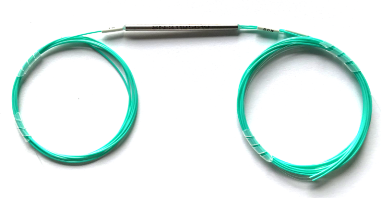
Two offers marked “PM isolator” can describe devices intended for very different positions in a laser chain. One may suit a low-power source; another may be a larger high-power assembly with a different loss allowance. When evaluating a PM optical isolator supplier, first identify the wavelength and the optical power at the location where the isolator will sit, then define the reverse-feedback limit and PM working axis. Feiyi’s PM 1064 nm fiber optic isolator and PM 1064 nm high-power isolator offer useful starting points for different power conditions; their similar names do not make them interchangeable.
Identify which laser reflection the PM optical isolator must suppress
Imagine a laser assembly that remains stable on an open bench but changes behavior when connected to a downstream coupling head. The procurement problem is not solved by adding a component with the largest isolation number in a catalog. The engineer needs to locate the reflected-light route, establish the relevant wavelength and decide where feedback protection belongs. An isolator is placed in a path where forward transmission is wanted and reverse propagation toward the protected source is unwanted.
Newport’s feedback-prevention application note explains the general reason optical isolators are used in fiber-based laser systems. Use that principle to describe the problem to the supplier. It does not establish that an isolator will fix every source fluctuation, and it does not replace the laser manufacturer’s requirements for the amount of feedback allowed at the source.
A 1064 nm PM isolator is not a substitute for a 1550 nm amplifier isolator
Feiyi’s standard PM 1064 nm isolator lists an operating wavelength of 1064 ±5 nm, PM1060 fiber and slow-axis operation with fast-axis cutoff. The PM 1310/1550 nm isolator family instead lists the telecom-band choices and PM1550/PM1310 fiber. Both families provide reverse protection, but the wavelength and fiber fields tie them to different optical circuits.
For an amplifier procurement team, the right comparison therefore begins within the relevant wavelength family. A device selected for a 1550 nm signal path should not be approved for a 1064 nm path because both have a cylindrical package or FC/APC options. Keep the required wavelength range on the purchase drawing and identify the optical position in the assembly. This also helps separate a pump-wavelength requirement from a signal-wavelength requirement when both are present in one project.
The origin of the reflection matters as much as the component label. If the system deliberately measures a returning signal, document the intended receive route before placing an isolator there. Protecting the source and collecting a return are different design objectives. The protection component must be located so that it suppresses unwanted feedback without blocking an optical signal the instrument needs.
A PM optical isolator supplier should quote the device for its actual power plane
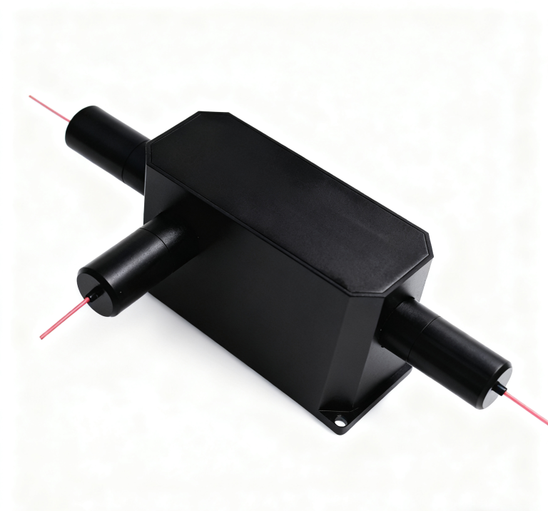
The standard PM 1064 nm isolator lists a maximum power handling of 300 mW. Feiyi’s high-power 1064 nm variant lists 2 W and different package dimensions. A buyer moving a source-protection component downstream of an amplifier should reopen that rating even when the wavelength remains unchanged. The location change can alter the power the device must carry and the mechanical space available for it.
The listed 300 mW device uses PM1060 fiber and offers single- and dual-stage choices. Evaluate it at the source or signal plane whose actual conditions fit the approved specification.
The listed 2 W device uses a larger enclosed package. Review its different forward-loss figures and housing dimensions before changing the approved assembly.
Average laser power does not define every pulsed operating condition
A power value expressed in watts does not by itself explain pulse duration, repetition rate, peak power or the conditions of an abnormal reflection. For a pulsed project, give the supplier those operating characteristics and request explicit confirmation for the selected variant. Do not turn a listed maximum power into an unverified pulse-damage threshold. The acceptable limit has to apply at the isolator’s location, with the actual fiber and termination.
Likewise, a claim that a product is “high power” is not enough to release an order. Feiyi’s PM 980 nm TGG-based high-power isolator is listed at 980 ±5 nm with a broad power-handling range. That range signals the need to confirm the exact build and operating conditions; it should not be treated as one universal rating for every device in the range. It is also a different wavelength product from the 1064 nm options.
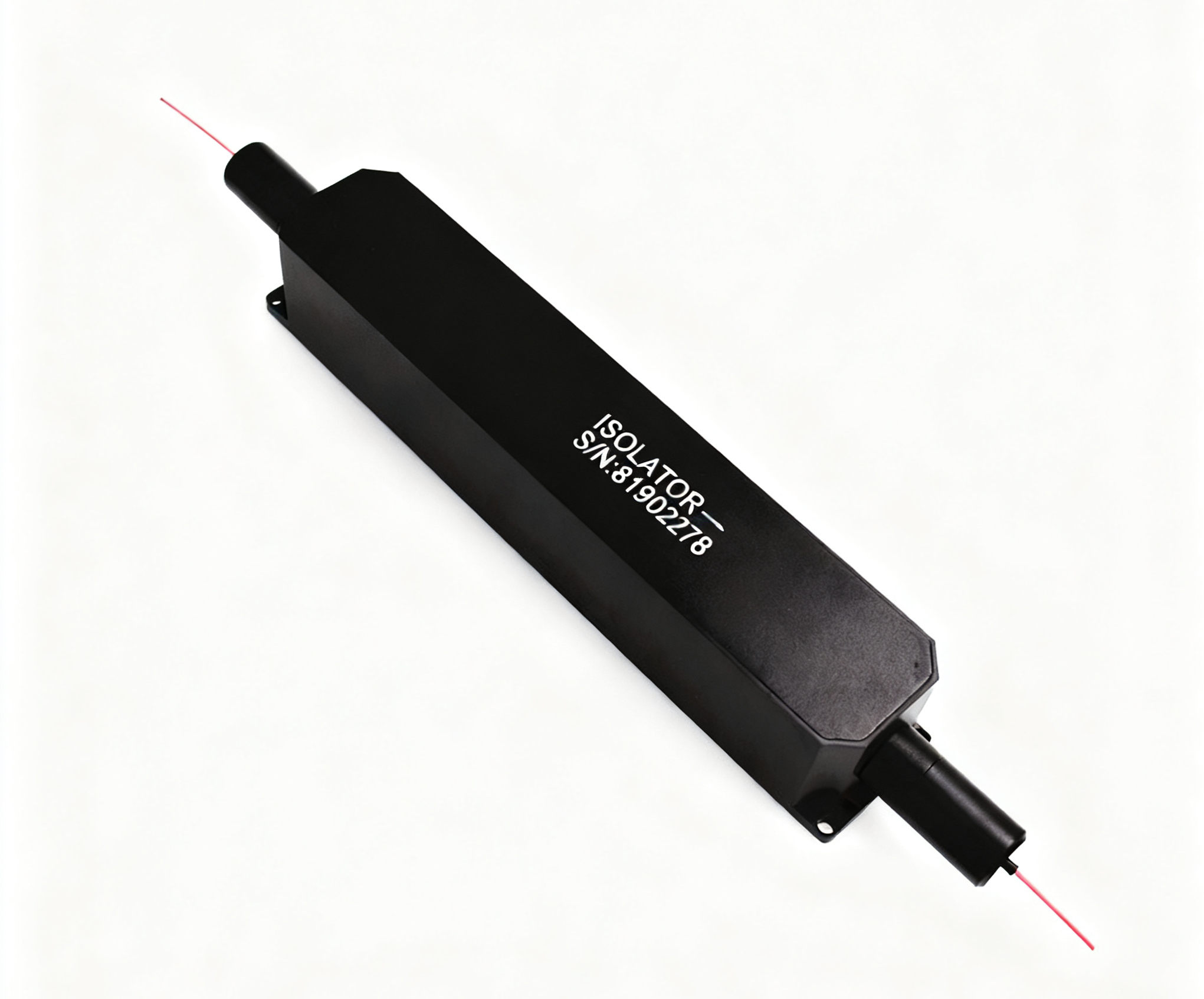
If a purchasing team compares the 980 nm and 1064 nm devices on enclosure size alone, it misses the first optical constraint. Instead, describe where each wavelength exists in the laser chain and which source it protects. The engineer can then compare relevant candidates while the purchaser keeps their order descriptions distinct. There is no benefit in consolidating unlike optical conditions under one vague “high-power PM isolator” line.
The 1064 nm high-power isolator housing changes with the selected stage
The high-power 1064 nm table lists a 33 ×17 ×11.5 mm package for the single-stage configuration and a 60 ×17 ×11.5 mm package for the dual-stage configuration. Those dimensions affect the component seat and available fiber-exit space inside a laser enclosure. If a prototype was built around the shorter body, adding a dual-stage isolator is a mechanical change as well as an optical one. Show the intended fixing points and lead direction on the approved drawing.
A replacement order should also identify the termination actually fitted to the laser chain. Feiyi lists connector options and minimum fiber-length information for these isolators, but the completed assembly needs a confirmed lead length and connector choice. If one side is intended for a splice and the other for an FC/APC interface, write the two ends separately. That avoids receiving a mechanically suitable housing with terminations that force a different assembly process.
Single-stage and dual-stage PM isolators spend the forward-loss budget differently
Feiyi’s standard PM 1064 nm table lists typical isolation of 35 dB for the single-stage configuration and 52 dB for the dual-stage configuration. The minimum isolation values are 28 dB and 45 dB respectively. At the same time, its listed maximum insertion loss changes from 1.8 dB to 3.2 dB. These values show why a stronger reverse barrier must be considered alongside the forward path the laser or amplifier can afford.
A dual-stage device may be relevant when the required reverse suppression is beyond the approved single-stage limit. It is less attractive when the forward power budget is already tight and the lower-isolation device meets the actual feedback requirement. Make that decision with the laser engineer’s acceptable-feedback limit, not an assumption that a higher catalog isolation number is always the best purchase.
Minimum isolation and maximum insertion loss belong on the same approval drawing
Typical results and acceptance limits serve different purposes. An offer based on typical isolation should be clarified if the project requires a minimum value for each delivered device. Similarly, the maximum forward loss should be stated with wavelength, temperature, axis and connector conditions. When those conditions differ between offers, the figures do not form a fair comparison until they are aligned.
Thorlabs’ isolator laboratory note demonstrates that transmission and isolation are separate characteristics to evaluate. The useful procurement lesson is to request the two results for the same approved conditions. Measurements from another manufacturer’s product cannot establish Feiyi performance, and an excellent reverse reading cannot compensate for a forward-loss result that exceeds your assembly’s allowance.
The high-power 1064 nm device should undergo its own loss review. Its product table lists different single- and dual-stage insertion losses from the standard 300 mW product. Do not carry the standard device’s loss allowance across a substitution simply because both operate near 1064 nm. Approve the exact stage and power configuration together, then record any consequences for amplifier gain or delivered output.
Preserve the slow-axis reference through the PM isolator and its jumper
Both the standard 1064 nm PM isolator and the telecom-band PM isolator describe slow-axis operation with fast-axis cutoff. That makes the launch orientation a functional requirement, not an optional labeling preference. If the incident light is not aligned as the assembly expects, forward transmission and polarization behavior may fail the project requirement even when the supplied component is working as designed.
Feiyi’s PM 1064 nm optical patch cord identifies PM1060 fiber and configurable axis orientation. Specify the orientation at the isolator connection and at the upstream source connection. A known connector polish does not automatically answer which PM axis is referenced to the connector key. For a removable assembly, that information needs to survive both ordering and remating.
PM1060 fiber and a single-mode 1064 nm isolator are different requirements
Feiyi also lists a separate 1064 nm SM isolator using Hi1060 fiber. It may be relevant to a non-PM optical path, but the matching wavelength does not turn it into a PM substitute. If the project needs an axis-preserving connection, retain the PM fiber and working-axis requirements rather than approving an ordinary single-mode device on wavelength and loss alone.
OZ Optics’ PM patchcord documentation explains the general alignment relationship between a PM fiber axis and a connector key. Apply that relationship when writing the interface drawing; do not copy the other supplier’s connector tolerance into the Feiyi order. The actual jumper, adapter and isolator should share a confirmed orientation convention.
Release the laser isolator sample only after both propagation directions are checked
During sample acceptance, test forward loss using the source wavelength and launch axis stated on the approved drawing. Then perform the appropriate reverse-isolation measurement under the agreed conditions. Label which result belongs to which direction. A total output-power reading from the complete laser chain is useful for system integration, but it cannot by itself identify the isolator’s insertion loss or reverse suppression.
Thorlabs’ insertion-loss measurement guidance describes referencing a measurement before adding the component under test. For this project, agree whether the acceptance setup includes the supplied connectors and jumper. That keeps a connectorized assembly from being judged against a bare-fiber reading without acknowledging the extra interfaces.
For the higher-power 1064 nm housing, confirm the selected dimensions and fiber exits against the mounting arrangement before the sample is shipped. Ask for connector end protection and a packing method that prevents the heavier housing from loading the attached fibers in transit. For the 980 nm assembly, approve its own mounting and handling arrangement separately. These are product-specific packing requests to agree, rather than a statement of Feiyi’s standard shipping process.
Feiyi’s PM fiber isolator discussion can help the project team compare the wider application context. Keep the order itself more precise: exact wavelength, PM fiber, working axis, stage, power conditions, permitted forward loss, minimum reverse isolation and connector arrangement.
Approve the supplier against the isolator plane you actually intend to build. If the sample meets the feedback requirement but exceeds the forward-loss allowance, the specification is still unresolved. If its average-power rating looks adequate but pulse conditions remain unconfirmed, that is also an open engineering question. Release the repeat order when the selected device, the PM jumper and both propagation-direction tests describe the same laser assembly.