2.5G DWDM SFP Transceiver Supplier: Preserve the Legacy Link Channel and Receiver
The spare is recognized by the equipment, but the legacy circuit still does not return. That situation calls for a channel-and-receiver review before another optic is ordered. A buyer working with a 2.5G DWDM SFP transceiver supplier should preserve the installed SFP service, configured DWDM center and two-end optical limits. Feiyi’s 1.25G/2.5G DWDM SFP family provides 2.5G 40 km and 80 km ordering rows for that review. Begin with the exact 2.5G configuration and the existing 100 GHz channel path.
For a maintenance buyer, the objective is to restore a known circuit. For an industrial equipment OEM retaining a legacy interface, the objective is to approve a repeatable component configuration. Both require more than matching the SFP housing. The rate, channel, receiver arrangement and host application should remain connected throughout the replacement test.
Follow the failure through three boundaries: the host must operate the required 2.5G service; the passive assembly must route the configured DWDM wavelength; the remote receiver must accept the delivered optical condition. Record the result at each boundary before deciding which component to replace.
Recover the exact 2.5G DWDM SFP configuration from the installed link
Feiyi lists XKSC-XX24-40BD at 2.5G and 40 km, with a DWDM wavelength entry, DFB/PIN, LC/PC and a DDM Y/N choice. XKSC-XX24-80BD is listed at 2.5G and 80 km with DFB/APD, LC/PC and DDM Y. The same table includes separate 1.25G rows. Preserve the data-rate column when identifying the spare.
The XX24 ordering rows distinguish 2.5G from 1.25G
Use the complete configured identifier and approved technical document, rather than a fragment of the shared family name. The ordering table’s DWDM entry does not identify every supplied channel. Obtain the exact center frequency or wavelength for the unit and reconcile it with the installed passive port. A shared prefix cannot serve as the complete optical identity.
A maintenance technician may have an old invoice that says only “DWDM SFP, 80 km.” That invoice does not establish whether the installed module was 1.25G or 2.5G, nor its selected channel. Recover the equipment service setting, old module label and passive assembly record before interpreting the invoice as a replacement specification.
A 100 GHz system needs the configured channel, not a CWDM substitute
The Feiyi DWDM family describes suitability for 100 GHz channel spacing. Its exact configured center should agree with the installed channel. The ITU-T G.694.1 DWDM grid is a reference for unambiguous frequency designation; it does not supply a particular module’s optical tolerance or acceptance result.
Feiyi’s 1.25G/2.5G CWDM SFP family belongs to a different wavelength-selection arrangement. Similar rate and connector entries do not approve it for a DWDM passive path. Keep the grid and the actual filter route inside the replacement decision rather than substituting a readily available lower-rate module by format alone.
If the host accepts the SFP, check the service mode before changing the fiber
The DWDM product lists SFP MSA, SFF-8472, a duplex LC receptacle and a single +3.3 V supply. These are relevant family interface details, but they do not supply a named host compatibility record. Confirm the required service rate and application with the equipment configuration and selected module approval.
Physical insertion and module recognition are narrower results than a successful service test. A host can report the presence of an optic while the intended service mode remains incorrect or unapproved. Keep the host observation separate from the external optical-path result. This makes the next troubleshooting step more specific than simply declaring that the module works or fails.
An OEM preserving a legacy interface in a new equipment revision should evaluate the selected SFP with that revision. A prior sample result on another board does not establish the same interface behavior after the host changes. Record the relevant board and service configuration when approving the module for repeat purchases.
Commercial and industrial case ranges should match the installed location
Feiyi lists 0 to +70°C for the commercial version and −40 to +85°C for the industrial version. These are module case-temperature entries. Evaluate the conditions at the optic, especially inside an enclosed or populated unit. Room ambient alone is not a complete case-temperature approval.
Retain the selected temperature version with the configured channel. If purchasing proposes a different version for availability reasons, confirm its optical and host approval. Do not expand the industrial range into an unsupported statement about humidity, vibration, environmental sealing or certification.
Trace the selected DWDM wavelength through the three-port filter
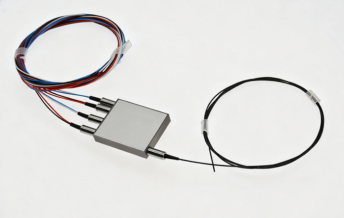
Feiyi’s 3-port DWDM device has common, transmission and reflection paths and includes 100 GHz and 200 GHz options. A replacement review should identify which path carries the service. The presence of a DWDM filter does not establish that the module was connected to the correct port or that the filter spacing matches the approved design.
For a service whose channel passes through several passive elements, recover the actual sequence. A circuit diagram should show the selected frequency from transmitter to far-end receiver, including each filter path it traverses. If the local transmit channel differs from the incoming channel, document both directions rather than treating the local module label as the identity of the entire circuit.

Consider a site where the passive assembly was replaced during earlier maintenance. The original circuit record may identify the right channel but an outdated port position. Verify the present assembly against its labels and approved map before replacing another SFP. A correct optic connected through the wrong route can reproduce the original service failure.
A nominal center match should also be checked against the configured filter passband and the selected module’s relevant optical tolerance. Request the required data when it is absent. Do not claim a complete operating-range fit from a family channel label and a filter’s nominal spacing alone.
Decide whether the 40 km or 80 km receiver row preserves the power window
The published rows distinguish DFB/PIN and DFB/APD receiver arrangements but do not supply the complete transmitter-output, sensitivity and overload values needed for a circuit calculation. Obtain those limits for the actual selected module and the opposite endpoint. The 40 km or 80 km label is not a substitute for that two-end review.
On the installed path, account for fiber attenuation at the selected wavelength, filter loss, connectors, splices and any planned reserve. Keep the calculation tied to the optical route already traced. A generic passive-loss value can hide an added filter or a reflection path whose loss differs from the selected transmission path.
On a short test connection, examine the maximum permitted receiving input. A longer-reach replacement may require a different bench attenuation arrangement from the old unit. Define the condition using the configured limits, and record the test arrangement so that the result is not later confused with qualification of the deployed circuit.
A field-service buyer replacing a failed 40 km-category optic with an available 80 km-category unit should treat the receiver-row change as an engineering question. It may be acceptable after review, but the distance label alone does not establish it. Retain the approval that connects the new row to the actual host, channel and receiving window.
If received power appears low, preserve the module and route identifiers while inspecting the external interfaces and filter assignment. If it appears unexpectedly high, compare it with the approved overload limit and attenuation arrangement. Both observations need a configured limit before they become evidence that the optic itself is defective.
Also identify whether the replacement is restoring one endpoint or changing both endpoints. With one endpoint unchanged, its receiver specification remains part of the new transmitter review. With both endpoints changed, approve the new pair explicitly. Two units carrying the same family description do not remove the need to verify their optical relationship through the installed passive route.
The duplex LC interface needs a direction record. Identify the transmit and receive connections from the module through any patch panel to the passive assembly. If the technician temporarily reverses or reroutes leads while investigating the fault, restore and document the final approved arrangement. A link failure caused by a direction error should not become a purchasing claim that a different receiver type is required.
For repeat orders, request the approved channel and receiver-row identity on the supplier’s configuration record. The family table uses a broad DWDM label rather than a full channel specification. Keeping the configured center with the delivered unit prevents a later purchasing operator from interpreting that broad label as permission to order any DWDM wavelength. The accepted sample and the production spare should remain traceable to the same optical approval.
Use SFF-8472 diagnostics to preserve a useful replacement record
The family lists SFF-8472 and digital diagnostic options in its ordering table. Confirm which diagnostics are supplied and how the host reads them. The 40 km Y/N choice should be explicit in the order if the maintenance procedure depends on diagnostics. A change to a non-DDM configuration should not be discovered only after dispatch.
Diagnostic observations can help compare the accepted sample, the removed module and the installed replacement. Record the host and the optical route used for each reading. They remain supporting observations, not a replacement for the approved optical acceptance method or proof that every part of the circuit has passed.
When a diagnostic reading and an external measurement disagree, investigate the measurement conditions and interface interpretation before assigning a failure. Preserve the data with the actual configured module identity. A result without its channel, receiver row and test path is difficult to use when a later technician repeats the review.
Keep legacy 2.5G spares separate from a 10G network upgrade
The 10G DWDM SFP+ transceiver is a different rate-and-host candidate. A network upgrade can retain a DWDM channel while changing the equipment and optical requirements. That broader change should have its own approval; it is not equivalent to restoring a legacy 2.5G SFP service.
Feiyi’s transceiver family overview helps frame the distinction. For a maintenance order, keep the required legacy service visible rather than allowing a newer product family to replace it by appearance or marketing description.
Agree shipment protection for the LC optical interfaces and configuration labels that retain rate, channel, receiver row, temperature and diagnostic choice. Confirm the technical document and dispatch arrangement for the selected version. The catalog does not prove ready inventory or a fixed replacement-delivery period for every configuration.
When the circuit is restored, keep the final normal connection map and approved SFP identity with the maintenance record. The next buyer should be able to order the same qualified configuration without repeating the channel investigation. If the host operates correctly but the passive route or receiver window remains unresolved, finish that investigation before consuming another spare.