Polarization Maintaining Fiber Components Supplier: Define the Interfaces Before Ordering
“Low loss, PM fiber, custom length” is not yet a buildable optical request. It leaves the supplier to guess the connector reference, fiber geometry and location where the optical performance matters. A polarization maintaining fiber components supplier needs those interfaces before it can assess a sample. Feiyi’s custom PM patch cords, custom PM single-fiber pigtails and custom PM collimators provide different starting points. First decide which end is connectorized, which end is an optical assembly interface and what the receiver must actually see.
A useful custom request distinguishes an offered ordering choice from a new feasibility question. Choosing a documented lead length is different from requiring a new optical tip geometry. Specifying an existing wavelength option is different from assuming that the same package works at an unlisted band. Keep these distinctions visible so the first sample resolves your engineering uncertainty rather than introducing a second one.
A polarization maintaining fiber components supplier needs two defined reference planes
Imagine a laser OEM connecting a PM source lead to a collimated free-space stage. At one end, the detachable connector establishes the axis reference and mating geometry. At the other, the collimator establishes a beam at a particular plane. A loss target without those two planes leaves open whether the measurement includes a connector pair, a free-space gap or coupling into another fiber.
Feiyi’s custom PM patch-cord ordering options include 250 µm, 900 µm, 2 mm and 3 mm lead styles, slow- or fast-axis choices and different input/output connector forms. Its wavelength entries include 780, 850, 980, 1064, 1310 and 1550 nm. Those choices help define a lead, but they do not define the collimator’s beam waist or the receiving aperture. Draw the assembly boundary explicitly before selecting the cable dimensions.
A PM patch cord and a PM pigtail solve different mechanical interfaces
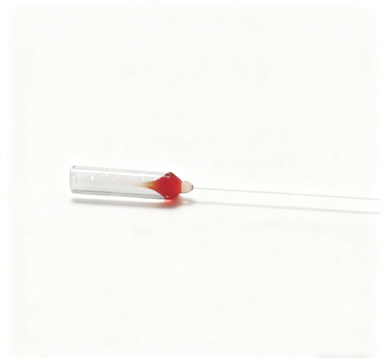
The patch cord is the appropriate starting point when the project needs detachable connector interfaces. The custom single-fiber pigtail instead lists compact ferrule dimensions such as 1.8 ×6.5 mm and 1.0 ×6.5 mm, with PM fiber options and antireflective coating information. It is relevant when the fiber end becomes part of another optical assembly. Do not specify a complete patch-cord connector where the housing expects a small ferrule.
The pigtail lists a maximum power entry of 500 mW, while the collimator range lists separate power options extending from 0.5 W upward. Selecting a higher-power collimator does not upgrade the pigtail used beside it. If the custom assembly combines these families, describe the power at each physical element and obtain configuration-specific confirmation instead of attaching the largest number to the whole build.
Custom optical interfaces must be frozen before the sample’s loss target
The custom single-fiber pigtail illustrates why its interface must be defined: it lists a minimum extinction ratio of 23 dB and PM980, PM1550 or PM1310 fiber options. Specify which applies to the requested wavelength and assembly. A common ferrule diameter does not establish equivalent mode or polarization behavior. If the receiving assembly already uses another fiber, treat the joint as an optical interface requiring review rather than assuming that a matching mechanical hole makes the fibers interchangeable.
Feiyi’s collimator ordering information offers C-lens and G-lens types, working-distance choices and connector or bare-fiber options. The telecom entries identify 1310 and 1550 nm with PM1310/PM1550 fiber. If the OEM changes working distance after approving the mounting envelope, the sample may require renewed optical and mechanical review. A lens-type code does not replace the beam requirement that motivated it.
Define the target beam at the useful plane: the aperture it must clear, the receiving optic or fiber, and the acceptable alignment range. A nominal beam-diameter entry below 0.5 mm is not a complete description of propagation through an arbitrary gap. The supplier should understand whether the priority is efficient fiber-to-fiber transfer, clearance through a small opening or illumination of another element.
The collimator’s working distance is not the length of its fiber lead
Working distance refers to the relevant optical spacing; fiber lead length refers to the cable routed back to the assembly. An engineer requesting a 200 mm gap and a one-meter lead should put those dimensions in different fields. Otherwise, a purchasing description can accidentally express a mechanical cable dimension as an optical design requirement.
OZ Optics’ collimator information and Edmund Optics’ Gaussian-beam explanation give useful background on beam propagation. They help frame the requested reference plane. Their device performance and optical designs should not be transferred into a Feiyi sample specification without its own approved configuration.
State both connector ends, polish, axis convention and cable routing. Use the custom PM patch-cord choices as the starting definition.
State ferrule or lens envelope, exposed fiber condition and the receiving plane. Use the pigtail or collimator family according to the assembly boundary.
A wedge lensed-fiber request begins with the source mode and tip orientation
A DFB laser package team may send a target coupling loss while omitting the orientation of the laser’s unequal beam axes. For that application, Feiyi’s wedge lensed fiber is a relevant discussion point: the product identifies DFB laser coupling and offers SM, MM, PM or customized fiber choices. The wedge direction must be tied to the source and mount reference, not left as an unmarked rotational freedom.
The wedge product lists a tip-radius range of 8–12 µm and a wedge-angle range of 60–120 degrees, with an applicable coupling far-field divergence range of 15–40 degrees. Those ranges are not a guarantee that every radius-angle combination suits every laser. Provide the laser’s optical requirements and the intended measurement geometry, then ask which configuration is feasible within the offered range.
Wedge tip radius and stripped coating length belong on the same assembly drawing
The optical end shape controls the coupling discussion, while the stripped length affects how the fiber can be supported in the package. The Feiyi wedge description offers customized fiber and stripped-coating lengths. If the fixture clamps where the coating was expected to remain, the sample can become difficult to install even when its optical end is suitable. Mark the support location and optical tip separately.
The same product describes direct processing of bare fiber without auxiliary adhesives. That is a stated processing feature of this product, not permission to declare the whole customer package free from adhesives or contamination. The final assembly may use its own bonding or sealing method. Ask the package engineer to separate the supplied tip condition from the method used to retain it.

OZ Optics’ lensed-fiber documentation offers background on using shaped fiber ends for coupling. For the proposed Feiyi sample, the controlling information remains the agreed fiber type, wedge geometry, exposed length and optical test arrangement. An external coupling result cannot establish the loss of your unbuilt package.
A customized filter WDM needs a port-by-port request
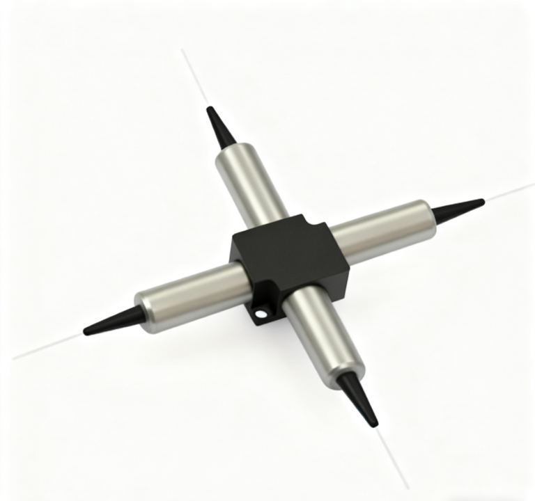
Feiyi’s PM filter WDM offers several wavelength-band combinations, including telecom pass bands with 980 nm or 1064 nm reflection bands. It also offers connector and fiber-length selections. For a custom module, list the common, pass and reflection leads individually. A drawing with only one “PM fiber” label does not define the fiber and axis behavior of each route.
This matters when a compact OEM enclosure forces one lead to be bare fiber and another to terminate at a front-panel connector. The internal splice interface and external connector interface have different handling and acceptance requirements. Ask whether that requested combination is available, and establish the test boundary for each channel. Do not assume that a standard all-connectorized performance condition describes a mixed-termination build.
Changing the WDM reflection band may require a new optical approval
A customer changing from a 960–990 nm reflected band to a 1020–1080 nm reflected band is changing the optical function, even if the 1520–1580 nm pass band remains. Review the selected fiber, wavelength limits and port test again. Carrying forward an old drawing with only the product name edited would hide the decision that the new sample is intended to validate.
The filter WDM’s published 300 mW maximum-power entry is also a reminder to define actual port power in a custom request. A custom connector or lead length does not imply approval for a higher-powered pump. If the source condition exceeds the listed entry, that becomes a specific feasibility question. The correct response is configuration review, rather than assuming that the word “custom” removes a limit.
Approve a custom optical sample by resolving the changed interface
A useful wedge sample comparison changes one specified geometry at a time while preserving the source, fixture and measurement plane. If two samples differ in wedge angle, exposed length and rotational mounting at once, the package team may not know which change affected coupling. This is a proposed comparison method, not a reported experiment. Agree the sample’s variable before ordering multiple variants that cannot be meaningfully separated during evaluation.
For the PM lead and collimator scenario, the sample should resolve the agreed connector axis and the beam at the receiving plane. For the wedge-fiber scenario, it should resolve source orientation, tip geometry and physical support. For the WDM, it should resolve the port bands and mixed termination. These are separate engineering objectives, so a universal “sample approved” note is less informative than an approval tied to the actual drawing.
When shipping the wedge sample, agree protection that prevents the exposed tip from contacting the container or bearing a handling load. For a collimator, define protection of the optical face and strain relief at the lead exit. For a PM patch cord, keep end and axis identification available without removing the connector’s protective cap. These are requested conditions to confirm for the actual sample, not claims about an undocumented standard package.
Feiyi’s discussion of customized wavelength-module solutions provides another example of configuration choices. For an optical assembly, freeze the changes that affect its interface before treating the sample as a repeatable order.
The custom patch-cord description notes that connectorized conditions can alter loss, return-loss and extinction-ratio allowances compared with unconnectorized conditions. If a sample was evaluated as bare fiber and the purchased lead adds connectors, revise the acceptance boundary with the manufacturer. Keeping the original numerical target while changing the measured path is not a neutral mechanical change; it can make a feasible optical request appear inconsistent.
Separate desired features from mandatory interfaces on the request. For a PM collimator, the mating envelope and receiving beam requirement may be mandatory while the preferred lead length can be adjusted. For a wedge fiber, source orientation may be mandatory while connector form remains optional. This lets the supplier discuss a workable configuration without silently trading away the part of the interface that the instrument actually depends on.
Release the next revision only after the drawing shows which unresolved question the sample answered and which conditions remain open. A request for a different wedge angle, working distance or WDM band should reopen that specific approval. That keeps custom manufacture focused on a defined optical job and prevents an attractive sample from becoming the specification for a different assembly.
Choose a polarization maintaining fiber components supplier by interface continuity across the assembly
A PM component family is useful only when its axis reference, wavelength and physical interfaces can be carried from one device to the next. A detachable PM patch cord may connect an instrument panel, a PM pigtail may terminate inside an optical subassembly, and a PM collimator may transfer that guided mode into free space. If the project also uses a PM filter WDM, circulator or isolator, keep the same wavelength and axis convention in the drawing so purchasing does not approve each item in isolation.
For a repeat order, record which Feiyi product family was accepted, the fiber type, wavelength, connector or ferrule form, lead length and any fast- or slow-axis requirement. That turns a broad supplier request into a reproducible PM assembly specification without inventing a single universal configuration for products that have different optical roles.