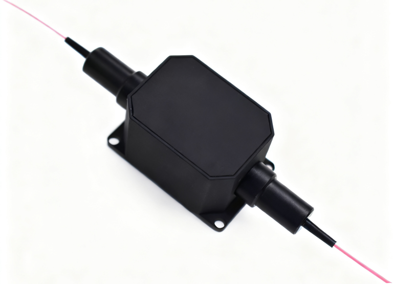
3 Port DWDM Filter Supplier: Review the Passband Before the OEM Filter Order
A 100 GHz filter and a 200 GHz filter can share a three-port outline while offering different passbands and loss limits. An OEM selecting a 3 port DWDM filter supplier should therefore approve the configured center, passband condition and transmission/reflection route before choosing the housing. Feiyi’s three-port DWDM device provides both spacing options for channel routing and add/drop applications. Start with the required spectral fit and the actual source conditions, then decide whether an individual filter or a completed assembly is the correct purchase.
This decision belongs to equipment designers and component buyers who need a particular wavelength route, not just a product labeled DWDM. The selected center must fit the source, the loss must fit the optical budget and the port arrangement must fit the assembly. A tube diameter or a familiar channel number cannot establish all three.
Define the DWDM center and −0.5 dB passband together
Feiyi identifies the channel wavelength by the ITU grid and lists 100 GHz and 200 GHz spacing. For the 100 GHz option, the passband at the −0.5 dB bandwidth condition is greater than 0.3 nm. For the 200 GHz option, it is greater than 0.5 nm. Keep the bandwidth condition with the figure when writing the purchase specification.
100 GHz spacing is not a 0.3 nm passband claim by itself
Spacing describes the relationship between nominal channels. Passband describes the spectral region of the selected filter under a stated loss condition. They are connected design quantities, but they are not interchangeable labels. A filter called 100 GHz still needs its configured center and passband evaluated against the source and operating requirements.
An OEM integrating a fixed-channel transmitter should obtain its relevant wavelength or frequency tolerance and compare it with the approved filter response. A nominal center match is only the first step. If the source moves under the application’s operating conditions, the filter review needs to cover the resulting spectral relationship rather than a single room-temperature point.
The 200 GHz option carries its own loss and bandwidth entries
Feiyi lists transmission insertion loss no greater than 0.7 dB for 100 GHz and no greater than 0.8 dB for 200 GHz. The reflection limit is no greater than 0.45 dB for both. A wider passband entry does not authorize copying the 100 GHz transmission-loss figure onto the 200 GHz version.
| Configured spacing | Passband at −0.5 dB | Transmission loss | Reflection loss |
|---|---|---|---|
| 100 GHz | >0.3 nm | ≤0.7 dB | ≤0.45 dB |
| 200 GHz | >0.5 nm | ≤0.8 dB | ≤0.45 dB |
Choose between these configurations using the actual network and source requirements. A wider option is not automatically suitable for a system whose channel plan requires a different spacing. Conversely, selecting a narrower grid label without checking spectral fit can leave the source operating outside the accepted portion of the filter response.
Ask a 3 port DWDM filter supplier to identify the configured ITU channel
The ordering examples include C21, C22, C23 and subsequent channel designations. Obtain the exact center frequency or wavelength together with the supplier’s channel name. Retain the three-port optical map on the same approved record. A family range does not tell the assembly technician which selected center belongs to the delivered unit.
ITU-T G.694.1 provides the DWDM frequency-grid reference. It helps reconcile center designation, but does not establish the supplied filter’s loss, spectral tolerance or conformity to every requirement of the buyer’s equipment.
Common, pass and reflection paths need a direction-specific drawing
The buyer should identify where the selected channel exits and where other light continues. Confirm the permitted direction and lead labels for the configured device. A photograph of the common housing cannot define this optical route. If the assembly uses the device in a particular direction, include that direction in the acceptance method.
For an add/drop design, document the full route rather than assuming that one three-port filter constitutes the completed function. The surrounding connections and any additional filters decide how light reaches the line and receiving interfaces. The individual device specification is one input to that design, not a substitute for the complete connection map.
A maintenance buyer replacing a filter inside an OEM enclosure should recover the original center, spacing and route before selecting a spare. Two filters with the same mechanical outline can carry different channels. Installing the wrong one can reject the intended signal while remaining an acceptable component for another application.
Read DWDM isolation as a channel relationship, not a universal port number
Feiyi lists adjacent-channel isolation greater than 30 dB and non-adjacent isolation greater than 40 dB. Preserve those distinctions when defining acceptance. A purchasing sheet that says only “40 dB isolation” would misrepresent the adjacent-channel entry and obscure which unwanted light is being evaluated.
Ask for the applicable measurement direction and spectral conditions for the configured filter. A test result should identify the selected channel and the unwanted channel relationship. The complete assembly can have several routes and connections; its output-to-output isolation should not be claimed solely from one filter’s non-adjacent number.
The table separately lists directivity greater than 50 dB and return loss greater than 45 dB. Keep those parameter names distinct from adjacent and non-adjacent isolation. They answer different optical questions and should not be combined into one generic rejection figure in a supplier comparison.
An equipment team evaluating a weak received channel next to a stronger channel should retain the relevant channel relationship in the test. The acceptance scope needs to reflect the actual design. A result for a distant channel does not, by itself, answer the neighboring-channel question that the receiver arrangement creates.
Count transmission and reflection loss in the actual OEM route
The selected channel may traverse its own transmission path after reflecting through upstream filters. Each route contributes a different listed limit. Identify that sequence before calculating the passive budget. One “DWDM filter loss” entry can hide the number of stages and the spacing option selected for the transmission stage.
For a 100 GHz design, use the relevant ≤0.7 dB transmission entry and ≤0.45 dB reflection entry where their configured conditions apply. For a 200 GHz transmission stage, use its own ≤0.8 dB entry. Add the actual external interfaces and other passive components separately rather than presenting a component-only total as a completed equipment specification.
The product lists channel ripple below 0.3 dB. Preserve the configured spectral conditions when reviewing that value alongside insertion loss. A nominal-center measurement is not the same acceptance scope as a required passband measurement. Agree which response the supplier’s evidence needs to demonstrate.
Consider an OEM rearranging filters to improve fiber routing inside a chassis. Moving the order of selected channels can change how many reflection stages each service traverses. Review the optical route after the layout change instead of assuming that using the same component list preserves every channel budget.
If a received-power test changes after assembly, separate the passive component from its new connections and mounting arrangement. Retain the configured channel and reference planes while investigating. A loss measurement without that context cannot reliably distinguish the filter from an added adapter, splice or incorrect route.
Compare three-port filters with DWDM modules, OADM and AWG assemblies
The DWDM module represents an assembled channel-routing scope. A buyer seeking a completed passive unit should review its configured channel map, package and assembly limits. The individual filter’s pass/reflection table should not be reused as the entire module specification.
The DWDM OADM module addresses a channel add/drop requirement. Compare the approved input, output and add/drop relationships with the network task. Its function is broader than receiving one selected three-port filter, and its acceptance should reflect the supplied assembly.
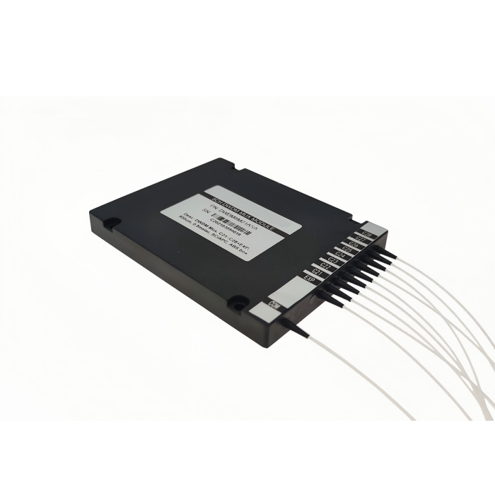
Feiyi’s 40-channel 100 GHz athermal AWG provides another multi-channel architecture to examine. Its channel count and arrayed-waveguide implementation distinguish it from individual three-port filtering. Evaluate the AWG’s own approved spectral profile and configuration rather than importing this filter’s bandwidth or loss limits.
The AWG listing contains entries that need a configured technical clarification before detailed numerical comparison. Keep the architecture discussion separate from disputed rows. The safe initial distinction is the supplied scope: an individual selected-channel filter, an assembled filter module, an OADM or a multi-channel AWG.
An OEM controlling its own internal routing may need individual filters and component-level acceptance evidence. An integrator buying a completed channel unit may prefer an assembly with its complete port map. Decide who owns the optical assembly design before comparing the catalog products by package photograph.
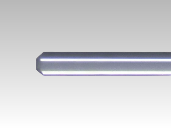
Place the Φ5.5 × 35 mm DWDM device in the real fiber layout
The performance table lists a Φ5.5 × 35 mm package. The ordering information also includes housing and cable choices. Confirm the mechanical drawing for the selected version instead of applying the tube outline to every possible package. The available space must accommodate the leads and intended connections as well as the component body.
The ordering options include bare fiber, 900 µm loose tube, larger cable choices, several fiber lengths and connector selections. State the delivered interface and polish in the order. If a component is to be spliced into an assembly, identify its protection and lead length; if it is connectorized, identify the mating arrangement and its contribution to the path.
Feiyi lists operating temperature from −20 to +70°C, insertion-loss temperature sensitivity below 0.005 dB/°C and wavelength temperature shifting below 0.002 nm/°C. Those entries should be evaluated at the component location with the source behavior. They do not independently establish complete equipment qualification over every environmental condition.
The maximum power-handling entry is 300 mW, with PDL below 0.1 dB and PMD below 0.1 ps. Confirm the actual source conditions and any additional requirements for the proposed application. These figures do not establish a PM axis specification or a limit for every pulsed or unusually high-peak-power operating mode.
Release a filter configuration that the assembly team can verify
The approval document should retain the configured center, spacing, optical map, package and lead terminations. Agree the spectral and port-specific test evidence required for the selected application. Keep component acceptance separate from the complete assembly result so that each supplied scope can be reviewed accurately.
For an order containing several centers, require labels and a packing list that let receiving staff distinguish the filters before connection. Agree protection for the chosen package and fiber leads during shipment. Confirm the actual channel mix and delivery arrangement; the product family does not prove stock of every configuration or a guaranteed dispatch period.
Feiyi’s DWDM mux/demux purchasing discussion addresses the broader assembly review. For this OEM filter order, resolve the narrower spectral and route requirements first. The right component is the one whose configured passband, isolation relationship and delivered interfaces fit the actual channel—not simply the one carrying the preferred grid label.