DWDM OADM Module Manufacturer: Define Add, Drop and Express Channels at Each Network Node
[Reading 56 lines from start (total: 56 lines, 0 remaining)]
DWDM OADM Module Manufacturer: Define Add, Drop and Express Channels at Each Network Node
A DWDM OADM module manufacturer should receive a node-level wavelength plan, not only a request for “4-channel” or “8-channel” DWDM. Feiyi’s DWDM OADM Module uses 100 GHz or 200 GHz ITU-grid channels and is intended to add or drop selected wavelengths while other wavelengths continue through the line. The product page lists 4- and 8-channel configurations, channel passband above 0.25 nm, insertion loss values up to 1.8 dB and 3.7 dB depending on the displayed channel configuration, adjacent isolation above 30 dB and non-adjacent isolation above 40 dB.
The purchasing question is therefore topological: which wavelengths enter or leave at this node, which wavelengths must pass through untouched, and is the module used on one direction or as part of a paired east/west network design? Once that map is clear, the buyer can select channel count, 100/200 GHz spacing, package, cable type, connector and fiber length without confusing an OADM with a simple terminal MUX/DEMUX.
A DWDM OADM module manufacturer needs the node’s add/drop table before the package is selected
For every local wavelength, mark whether the node adds traffic, drops traffic or performs both functions. Then mark the express channels that continue to the next site. This table should use actual ITU channel identities rather than “Channel 1–4,” because the same four-channel hardware concept can be built around different wavelength groups.
Feiyi’s ordering structure supports MUX, DEMUX and MUX+DEMUX configurations. A node that adds on one direction and drops on another should make that traffic direction explicit so port labels and patching are not left to installation interpretation.
An express wavelength should appear in the node drawing even when no local patch cord touches it
Express channels are part of the optical budget because they still pass through the OADM filters. Leaving them off the drawing makes later expansion difficult and can hide how many OADM nodes a through-channel has traversed.
100GHz and 200GHz spacing should match the existing DWDM line rather than the number of local services
Feiyi offers the DWDM OADM family at 100 GHz and 200 GHz channel spacing. This choice must match the carrier plan used on the surrounding network. A site with only two local services may still need a 100 GHz OADM if the trunk uses a 100 GHz grid; local channel count and network spacing are separate decisions.
If the line is being migrated from 200 GHz to 100 GHz, treat the OADM replacement as part of the wavelength-plan change. Do not assume an old add/drop module can remain because its local wavelength labels look similar.
Channel spacing is an end-to-end network property at an OADM node
The transmitter, terminal mux, intermediate OADM and receiver all need compatible channel centers and filter behavior. A purchasing team should not change spacing at one node independently of the rest of the link.
The passband above 0.25 nm should be checked against transmitter tolerance and cascaded OADM nodes
Feiyi lists channel passband above 0.25 nm at the -0.5 dB bandwidth condition shown on the product page. A single node may have comfortable margin, but a through-channel can cross several wavelength-selective components. The network engineer should consider the cumulative filter narrowing along the actual route.
For a long chain of add/drop sites, identify the worst express path and compare its transmitter drift and spectral width with the filters it encounters. The OADM should be approved from that route rather than from the easiest local channel.
Insertion loss should be accumulated by route, not quoted once per network
The Feiyi table shows insertion loss up to 1.8 dB for one displayed four-channel case and up to 3.7 dB for a higher-channel case. The exact value used in a link budget should be tied to the ordered configuration. A local add channel may pass through fewer filter stages than an express wavelength that crosses several OADM sites.
Build the optical budget per wavelength route. Include the terminal MUX/DEMUX, each OADM encountered, connectors, splices and any amplifier or monitoring component. This prevents a network from passing on the first site and failing after more add/drop nodes are deployed.
Adjacent and non-adjacent isolation should be reviewed where local transmit power is high
Feiyi lists adjacent isolation above 30 dB and non-adjacent isolation above 40 dB for the demultiplexing paths shown. These values help protect a dropped receiver from neighboring DWDM carriers and help keep a newly added transmitter from leaking into other channels.
At a node where one local transmitter is much stronger than the incoming express traffic, compare channel powers as well as isolation. An isolation figure has more meaning when the engineer knows what interfering power may be present at the neighboring wavelength.
A local add transmitter should not be commissioned without checking its effect on the express line
After adding a new wavelength, verify both the intended channel and representative neighboring channels downstream. This catches patching errors, abnormal launch power and unexpected leakage before the site is handed over.
Temperature sensitivity matters when OADM modules sit in roadside or access cabinets
The product page lists insertion-loss temperature sensitivity below 0.005 dB/°C and wavelength temperature shift below 0.002 nm/°C, with operating temperature from -5 to +75 °C and storage from -40 to +85 °C. These are relevant for passive add/drop nodes deployed outside climate-controlled data rooms.
If the cabinet has its own thermal range, compare that environmental specification with the OADM rather than assuming a telecom rack condition. Temperature can also affect other parts of the link, so the module should be qualified as part of the installed node.
PDL, PMD, directivity and return loss should remain in the node acceptance file
Feiyi lists polarization-dependent loss below 0.1 dB, polarization-mode dispersion below 0.1 ps, directivity at least 50 dB and return loss at least 45 dB. These parameters do not replace the channel-map and insertion-loss checks, but they help describe how transparently the OADM sits in the optical line.
For a high-speed DWDM system, keep the PMD and PDL values with the approved module even if the first deployment has generous margin. Later transceiver upgrades can make previously secondary parameters more important.
ABS, LGX and 1U rack packaging should follow who will service the node
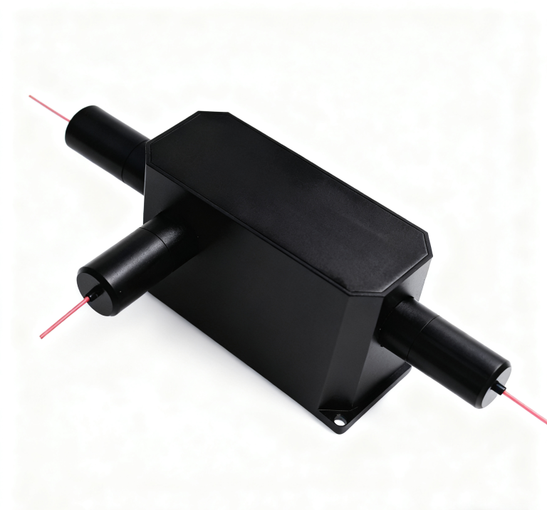
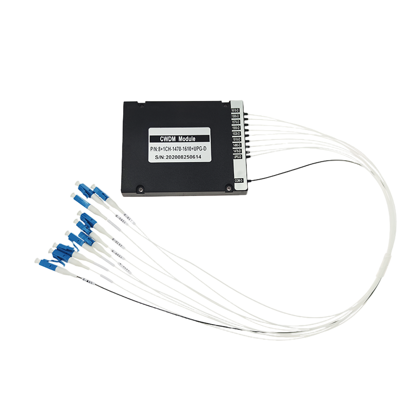
Feiyi’s ordering information includes ABS-box, LGX and 19-inch 1U rack options. An embedded OEM module may favor a compact ABS package. A field-accessible telecom node may benefit from LGX or rack presentation where ports and labels can be serviced without opening a separate enclosure.
The package choice should be made with fiber routing, connector access and site maintenance in mind. A compact module is not automatically the best option if technicians cannot identify the add and drop ports after installation.
Connector and cable codes should match the node patch plan before factory termination
Feiyi lists 900 µm loose tube, 2.0 mm and 3.0 mm cable options together with LC/UPC, LC/APC, SC/UPC, SC/APC, FC/UPC and FC/APC terminations. A field node should use the connector polish and cable style already supported by its patch panel or splice practice.
Put connector identity into the add/drop table. A label that says only “Drop C37” is incomplete if the technician still has to guess which port family or polish belongs at the receiver.
MUX+DEMUX packages need directional labels that cannot be read backwards
If one housing contains both functions, use port names that show line direction and add/drop role. A correct wavelength connected to the wrong directional port can create a service fault that looks like a filter problem.
Commissioning should prove one local add, one local drop and at least one express channel
A practical site test should demonstrate the three jobs the OADM performs. Verify that a local transmitter is inserted into the intended wavelength, that a local receiver gets the intended dropped wavelength, and that a representative express carrier continues through the node within the expected loss. If the site uses more channels, extend the test according to the acceptance plan.
This is more informative than measuring one convenient port because it validates the topology rather than only the component.
Adding another OADM node should trigger a fresh worst-path loss review
As a ring or chain grows, an express wavelength may encounter more OADM filters than it did during the original design. Before installing another node, update the loss and passband cascade for the longest through-route. A module that is acceptable by itself can still consume the remaining system margin when repeated many times.
This is especially important when the network was initially deployed with spare optical budget that has gradually been used by connectors, repairs or additional passive devices.
A DWDM OADM service spare must preserve the exact wavelength group and port roles
A spare described only as “4-channel 100G OADM” can be wrong for a site if its selected ITU channels differ. The maintenance record should include channel identities, add/drop direction, configuration, package, connectors and cable lengths. If the site uses MUX+DEMUX in one housing, that topology should be part of the spare description.
For networks with several sites, do not assume one spare fits every node unless the wavelength groups are intentionally standardized.
A repeat order should reproduce the node wavelength map rather than the generic OADM family
Once the first site is accepted, retain the 100 or 200 GHz grid, actual ITU channels, add/drop/express map, MUX/DEMUX configuration, agreed passband and loss values, isolation requirements, package, cable type, connector polish and fiber length. Also record the route-level budget used to approve the node so later expansion can be checked against the same engineering basis.
Feiyi’s broader DWDM MUX/DEMUX article focuses on terminal multiplexing. An OADM belongs in a different discussion: its value is letting selected wavelengths enter or leave an intermediate site without terminating the whole DWDM line.
Fault isolation should distinguish a dropped-channel problem from an express-path problem
When one service disappears at an OADM site, the troubleshooting sequence should use the node map. First determine whether the affected wavelength is locally added, locally dropped or only passing through. A failed local patch or transceiver can affect one add/drop service while the express path remains healthy; a line-port or filter issue can affect wavelengths continuing to the next site. Keeping these roles visible prevents technicians from replacing the whole module for a fault outside it.
For a multi-node network, record optical power before and after the OADM at commissioning. Those reference values give maintenance teams a useful comparison when a later fiber repair or connector contamination changes the node loss.
Network expansion should reserve physical ports and wavelength identities before new services arrive
If a four- or eight-channel OADM is installed with only part of its local capacity active, label reserved ports and their planned ITU channels from the beginning. This avoids later reusing a port that was intended for a future service and keeps the express-channel documentation consistent as the site grows.
When the planned local demand exceeds the installed OADM channel count, review whether the next step is a larger OADM, another module or a different node architecture. Adding unrelated filters around the original device can consume passband and loss margin that was not part of the first link design.
[executed on device: SK-20260121JOTG (a251fff9-956e-47b5-9307-14fb53329ed2)]