PM 1550nm Polarization Beam Combiner Supplier: Define Both Inputs Before the Common Output
A PM 1550nm polarization beam combiner supplier should know which two polarization states are being combined and what fiber type arrives on each input. Feiyi offers both PM 1550nm 1×2 and PM 1550nm 2×2 Polarization Beam Combiner/Splitter products. The 1×2 form lists 1550 nm with a ±40 nm range, typical insertion loss of 0.4 dB, maximum 0.6 dB and minimum extinction ratio of 22 dB. The 2×2 form uses a different topology and package and lists 0.6 dB typical, 1.0 dB maximum and 20 dB minimum extinction ratio.
For a buyer combining two polarization-defined paths into one output, the important first step is not to choose 1×2 or 2×2 from a catalog picture. Draw the two source paths, label their polarization relationship, show the common output and identify whether any reverse or additional route is required. The supplier can then match topology, fiber, power class and package to an actual optical architecture.
A PM 1550nm polarization beam combiner supplier should receive both input-state definitions
A polarization beam combiner is useful when two appropriately oriented polarization states need to share one output fiber. If the two incoming states are not defined, the combiner cannot be evaluated only from total output power. The engineering file should identify the state associated with each input, the axis reference at the connector or splice, and the expected output interface.
This is particularly important in coherent optical experiments, fiber gyros and sensing systems where the two channels may originate from separate paths. A wiring diagram that labels them simply “Input A” and “Input B” can be insufficient if the polarization relationship is what makes the combination work.
The common output should be named by its downstream job, not only by port number
If the combined output feeds a sensor, test instrument or another PM component, put that function on the diagram. The downstream fiber type and axis convention can determine whether the output should be standard single-mode or PM fiber. A combiner supplier should not have to infer that interface from a generic 1550 nm label.
The 1×2 and 2×2 1550 nm devices are different topologies, not package options
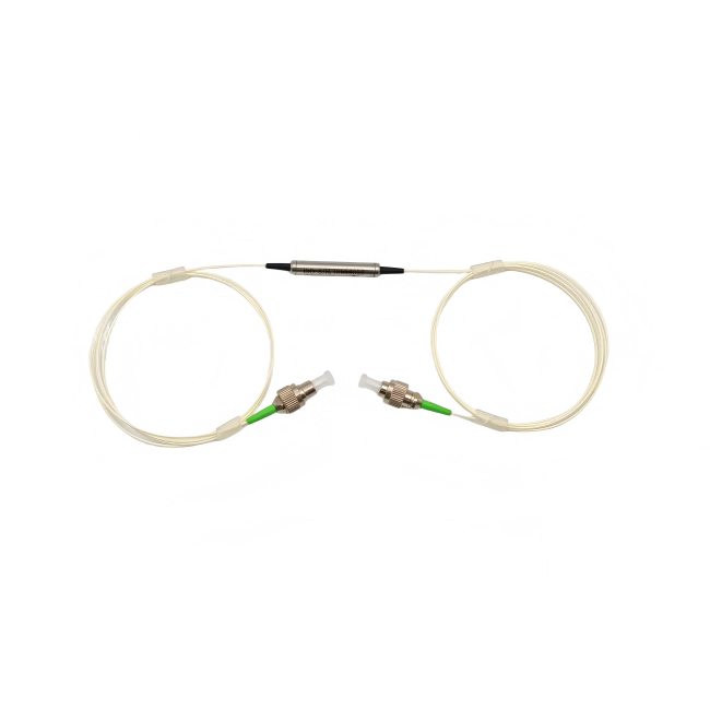
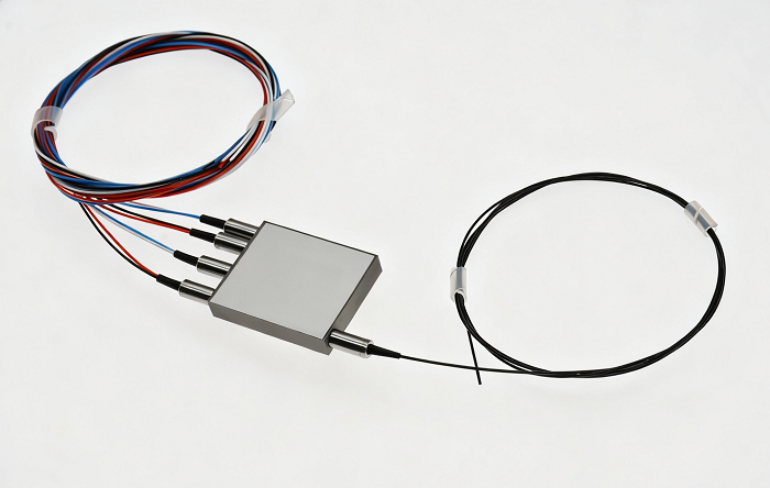
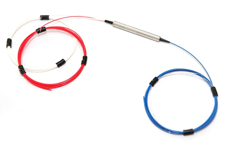
The Feiyi 1×2 product uses a cylindrical package around 5.5 mm diameter with L35 or L50 lengths. The 2×2 page lists rectangular packages around 14 × 12 × 8 mm or 12 × 12 × 10 mm. The mechanical difference reflects a different optical topology. Select 2×2 only when the system actually needs the additional port relationships.
In a compact instrument, the cylinder may be easier to route inline. A 2×2 architecture can offer additional flexibility but needs more pigtail management and a larger body. The buyer should compare topology and enclosure layout together rather than upgrading to 2×2 simply because it appears more versatile.
A 2×2 combiner needs a complete route map before all four fibers are bundled
Once four similar pigtails enter a harness, port identity can become difficult to recover. Label all ports during incoming inspection and verify the intended route before mechanical bundling. A correct 1550 nm component connected to the wrong ports can create a weak or unexpected output without any defect in the device itself.
Feiyi’s 1550 ± 40 nm range should be checked against both source paths
The Feiyi pages list 1550 nm with a ±40 nm operating range. If the two inputs come from different sources or channels, confirm that both fall within the selected component’s intended range. A combiner used in a tunable research setup should be qualified across the wavelengths that will actually be used, not merely at a nominal 1550 nm center.
DK Photonics’ 1550 nm 2×2 combiner/splitter documentation provides external industry context showing that topology, bandwidth, insertion loss, extinction ratio, fiber type and power are specified independently for this component class. Its numerical values belong to DK’s device; Feiyi’s current page remains the source for the Feiyi order.
Insertion loss and extinction ratio should be allocated to the combined path separately
For Feiyi’s 1×2 1550 nm device, typical insertion loss is listed at 0.4 dB and maximum at 0.6 dB, with minimum extinction ratio of 22 dB. For the 2×2 version, typical and maximum insertion loss are 0.6 and 1.0 dB, with minimum extinction ratio of 20 dB. The buyer should keep the values attached to the selected topology.
Total output power alone can hide a polarization problem. Two input beams may produce the expected total level while the polarization relationship is not what the downstream device requires. Conversely, a good extinction-ratio result does not eliminate the need to check forward loss. Treat them as separate acceptance conditions.
Combining two sources requires three identities on the test record
Record Input 1, Input 2 and the common output as separate paths. Add the polarization reference for the two inputs and the fiber/connector condition of the output. That is more useful for later troubleshooting than a single note saying “combiner passed.”
SM-28E and PM1550-XP options should be assigned by port, especially on mixed-fiber builds
Feiyi lists SM-28E or PM1550-XP fiber choices. A system may intentionally combine two PM inputs into a standard single-mode output, or it may need PM fiber throughout. The order should state the fiber type expected on each functional port instead of asking for “PM pigtails” without qualification.
If a standard single-mode output is used, the downstream system should be designed for that interface. If a PM output is required, preserve the axis reference into the next component. Changing from one fiber scheme to another during a redesign should trigger a new integration review, even if the optical body remains a 1550 nm combiner.
Connector keys and splice marks should use the same axis convention as the two inputs
Feiyi lists slow-axis operation with fast-axis cutoff. The mechanical reference at a connector or splice should correspond to the intended polarization state. If one input is rotated relative to the approved convention, the device may not combine the states as the system designer expected.
For repeat production, include an axis sketch that an assembler can follow without needing the original lab setup. That reduces reliance on tribal knowledge when the build moves between technicians or facilities.
Power classes from 0.3 W to 10 W should be selected for the sum and distribution of the two inputs
Feiyi lists average-power ordering options of 0.3, 1, 2, 5 and 10 W. In combiner use, the buyer should consider the power arriving from both inputs and the condition at the common output. Do not select a power class from only one source path if the combined optical level is higher.
Connectorized high-power builds deserve particular care. Feiyi lists FC/PC, FC/APC, SC/PC and SC/APC options along with bare-fiber configurations. Confirm the allowed power for the exact termination being quoted; do not assume every connector option supports the highest family power simply because 10 W is available somewhere in the ordering matrix.
A two-source test should include the highest credible simultaneous operating condition
If the instrument normally drives both inputs together, qualify that condition rather than testing each source separately and assuming the combined case is covered. For a system that alternates between inputs, document that operating mode instead. The supplier needs to know the real optical use case, not just the maximum rating of each independent source.
The 1550 nm combiner belongs beside PM patch cords and polarizers, but it does a different job
Feiyi’s PM 1550nm Optical Patch Cord carries a polarization-maintaining connection between modules. The PM 1550nm In-Line Polarizer selects a polarization state. The PM 1550nm Circulator routes light directionally. A polarization beam combiner combines defined polarization paths. All may appear in the same 1550 nm instrument, but none is a drop-in substitute for another.
Writing the optical function beside each BOM line is a simple way to prevent a purchasing team from matching parts only by wavelength and connector.

Two-input source balance should be documented before a combiner is judged by total output power
A common troubleshooting mistake is to measure the combined output, see the expected total optical level and conclude that the combiner is functioning correctly. If one source has drifted high while the other is low, the sum can look normal even though the intended two-state balance has changed. Record the individual input powers at the same time as the common output when the application depends on both sources.
This is especially useful during a supplier qualification run. The buyer can distinguish a source imbalance from a device loss problem and avoid rejecting a combiner because the two input lasers were not operating at their approved levels. For a coherent or sensing system, retain the input-state identity with those readings so the measurement can be reproduced later.
A distributor should not merge 1×2 and 2×2 stock under one 1550 nm combiner description
The 1×2 and 2×2 Feiyi products have different insertion-loss values, extinction-ratio limits and package geometries. They should therefore remain different inventory identities even if both can be described as PM 1550 nm polarization beam combiner/splitters. A customer who qualified the 1×2 cylinder should not receive the 2×2 rectangular device as a “compatible upgrade” without engineering review.
Likewise, power grade, fiber type and connector polish should remain visible in the stock record. That makes a warehouse substitution detectable before the part reaches a polarized optical system where the difference can be much harder to diagnose.
Combiner replacement should preserve the downstream fiber interface as carefully as the two inputs
Most selection discussions focus on the two incoming polarization channels, but the common output is the interface that the rest of the system sees. If that output changes from PM1550-XP to SM-28E, or from a splice to an FC/APC connection, the downstream optical behavior and service procedure have changed even if the combiner core is equivalent.
Include the common-output fiber and termination in the controlled configuration and inspect it before installation. A mechanically compatible replacement that changes the downstream interface should be treated as a redesign item, not as routine stock replacement.
Receiving inspection should test the combiner in the direction used by the product design
Although a beam combiner/splitter can be reversible in principle, the production instrument has a specific direction of use. Build the receiving test around that direction: apply the two approved input states, verify the common output, and check the loss and polarization behavior required by the system. A reverse-direction demonstration does not replace the installed-use test.
Feiyi lists operating temperature from -10 to +75 °C and storage from -40 to +85 °C. If the combiner is mounted in a wide-temperature sensor or telecom enclosure, include the relevant range in qualification. For a room-temperature laboratory instrument, keep the environmental test proportional to the actual application instead of adding generic checks that do not inform the purchase.
Repeat orders should preserve the relationship between the two inputs, not just the 1550 nm part name
After the first unit is approved, keep the topology, 1550 ± 40 nm range, input-state definitions, port-specific fiber types, slow-axis reference, insertion-loss and extinction-ratio conditions, power class, package, connectors and pigtail lengths in one configuration record. A repeat request for “PM1550 combiner” is too short to reproduce the optical interface reliably.
Feiyi’s polarization beam combiner manufacturer article provides broader context for output-state definition, while the 1×2 and 2×2 product pages provide the actual Feiyi options. A useful supplier handoff should let a reader identify the two inputs, their polarization relationship and the common output without reopening the original experimental notebook.
That level of detail is what protects the design when the system moves from prototype to production, from one assembler to another, or from the first order to a replacement several months later.