Ask a Fiber Polarization Beam Combiner Manufacturer Which States Will Share the Output
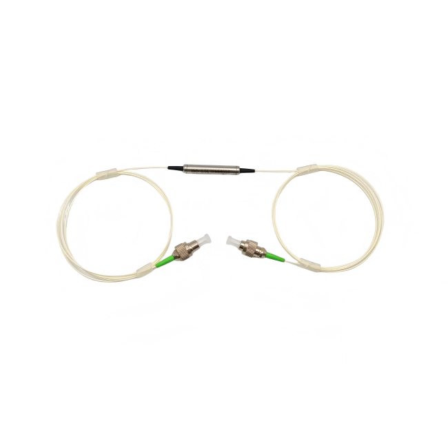
Two source fibers entering one package do not tell you what emerges from the common output. Before evaluating a fiber polarization beam combiner manufacturer, decide whether your project must combine orthogonal polarization states, combine different wavelengths or produce one selected polarization. Those are different optical jobs. Feiyi’s 1550 nm 1×2 polarization beam combiner/splitter is a starting point for a telecom-band polarization route; its 1064 nm version addresses another wavelength band. Confirm the port-by-port fiber and axis drawing first.
A source-module engineer and an amplifier purchaser may both ask for a “combiner,” yet need different parts. The first may deliberately carry two orthogonal states into a common route. The second may need to join a pump wavelength and a signal wavelength. Matching the noun on a purchase order cannot resolve that difference; the input states and wavelengths have to remain part of the component definition.
A fiber polarization beam combiner manufacturer needs the intended common-output state
In the general polarization-combining arrangement, two appropriately aligned orthogonal inputs share an output route. The output intentionally carries the contributions selected from both inputs. It should not automatically be described as a single highly pure linear state. If downstream equipment accepts only one polarization, determine whether combining orthogonal inputs serves that equipment at all. This question comes before comparing a device’s insertion-loss entry or selecting a power option.
Feiyi lists a 1550 ±40 nm operating band, typical insertion loss of 0.4 dB and maximum insertion loss of 0.6 dB for its 1550 nm 1×2 product. It lists SM-28E or PM1550-XP fiber choices. Those entries help identify a candidate, but they do not assign the common port or the axis of every lead. The published working-axis wording should be resolved into an approved drawing for the actual combining configuration.
SM-28E and PM1550-XP at the common port require different downstream assumptions
An OEM source module may feed a polarization-insensitive stage after combination. Another may need a stable reference to the two axes of a PM output. Do not specify all leads as SM or all as PM without considering those roles. Ask which fiber is used on each input and common output, which input state couples to which output axis, and what measurement route the specified extinction ratio describes.
The product’s minimum extinction-ratio entry of 22 dB at 23 °C is not a promise that two active orthogonal sources become one 22 dB-pure common-output state. A polarization performance value needs its test configuration. Separate the leakage of an intended input-to-output route from the relative powers of two states that the design deliberately combines. Otherwise a correct dual-state output can be mistaken for a failed polarizer.
PM polarization combining is not wavelength combining or phase locking
For an amplifier assembly that joins wavelengths, Feiyi’s PM filter WDM is the more relevant family to evaluate. Its listed band pairs include a 1520–1580 nm pass band with a 960–990 nm reflection band, and another pairing with 1020–1080 nm reflection. These identify wavelength-selective routes. A polarization combiner selected only by center wavelength does not establish the same pass/reflection function.
Conversely, a WDM does not answer which orthogonal polarization states should share one output at the same wavelength. If a source module has that requirement, establish its polarization route explicitly. The manufacturer discussion should show both wavelength and state for each input, leaving no ambiguity about whether the part is selected by spectral filtering or polarization separation.

Combining optical power does not establish a coherent single-field output
A purchasing specification sometimes asks a passive combiner to deliver the “same laser, twice the power.” That language leaves the coherence and accepted output state undefined. A passive polarization-combining route does not itself lock independent sources together. If the system needs phase control or a particular coherent field, those requirements belong to the source architecture and its actual validation, not to an assumed property of a fiber combiner housing.
Fujikura’s polarization-combiner information provides useful background on this component class. AFW’s combiner/splitter documentation also shows why port fibers are part of the configuration. Their application examples and device ratings are not Feiyi performance evidence; use them to clarify the required function, then approve the selected Feiyi route.
1310, 1550 and 1064 nm combiner versions should be compared within their own bands
Feiyi’s 1310 nm 1×2 combiner/splitter lists a ±40 nm band and 0.4/0.6 dB typical/maximum insertion loss, with SM-28E or PM1300-XP fiber options. The 1550 nm entry has the same listed loss values but different wavelength and PM fiber identification. That resemblance does not make the two variants interchangeable in an installed source module.
The 1064 nm version lists ±20 nm and 0.6/0.8 dB typical/maximum insertion loss. Its fiber information includes PM980 and another separately named option. For a PM design, confirm the selected PM fiber rather than assuming that every listed fiber label establishes equivalent polarization preservation. A change from telecom to a 1064 nm source should reopen fiber, coating and band approval, even if the packaging remains familiar.
The 1064 nm source module needs an operating band, not just a nominal laser label
An instrument designer considering a source with drift or tuning should specify the required operating interval. Compare that interval with the selected combiner’s listed band, and identify the performance limit needed across it. A nominal 1064 nm center does not prove acceptance at every proposed tuned wavelength. The engineer should also preserve the measurement temperature when relying on an extinction-ratio entry stated at 23 °C.
For a distributor offering these wavelength variants, keep each wavelength and fiber configuration as a distinct item. Similar housings can conceal different band limits and fiber choices. A clear unit label should allow the assembly team to identify a 1310, 1550 or 1064 nm component without energizing it as an identification test. Confirm availability and delivery for the selected version rather than treating the family list as proof of inventory.
A downstream inline polarizer changes the reason for combining two states
Feiyi’s 1550 nm inline polarizer passes the slow-axis state and rejects the fast-axis state. It can be relevant if the intended output needs one selected polarization. However, placing it after a route designed to combine orthogonal inputs can reject part of the very power you intended to use. Draw the accepted and rejected contributions before assuming that the additional polarizer improves the desired result.
For a hypothetical receiver accepting only one linear state, the better question may be whether the second source should be combined by polarization at all. For a downstream polarization-insensitive stage, preserving both contributions may be intentional. These buyers should not receive the same explanation of a “high extinction ratio output.” Specify the useful state at the actual receiving interface and choose the optical architecture accordingly.
Single-state transmission and dual-state power delivery need different acceptance tests
For a single-state route, identify the passed axis, rejected leakage and delivered power under the defined input state. For a dual-input combiner, measure the relevant route from each input with the other source condition controlled, then assess the intended simultaneous operation. Do not use a polarizer-style purity measurement to reject a deliberately dual-state common output without first defining what the receiver requires.
OZ Optics’ polarization-measurement application note gives background on launch alignment and measurement. The practical procurement implication is to document the input condition and analyzed output state. A test number without those conditions cannot distinguish unwanted leakage from a useful second input contribution.
Combiner power and fiber-end protection belong to the selected assembly
For a selected 1×2 combiner, agree how power is assigned to the approved routes before choosing its option. Identify whether the rating is being applied to one input, the common route or the specified operating arrangement. The two sources may have unequal powers, and one may be absent during startup. The engineer should describe those conditions so the manufacturer can evaluate the actual selected device rather than interpreting a single total-power number differently.
The Feiyi 1×2 wavelength entries list power options of 0.3, 1, 2, 5 and 10 W. Treat these as options requiring a selected build, not one universal rating. Specify the power arriving from each source, simultaneous operation and any pulse conditions. The combined route and its terminations need approval for the intended condition; choosing a higher number on one row does not establish every fiber-end condition.
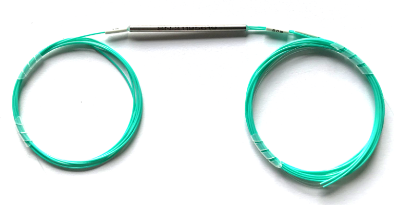
Package choices include cylindrical dimensions of 5.5 mm diameter by 35 or 50 mm length, with fiber-length and connector options. Confirm how the chosen unit fits the source module, where the leads exit and how the common route is identified. The small housing should not be used as a handle for a tangle of unsupported fibers during receiving. Agree end protection and separated, labeled lead loops for the actual supplied configuration.
Preserve axis references when the assembly team mounts the component. Rotating a housing or routing a fiber is not the same operation as redefining a connector’s key-to-axis relation. The approved diagram should identify the reference used for each detachable interface. If assembly changes alter that reference, update the interface definition before attributing a changed output state to the combiner alone.
For the 1550 and 1310 nm versions, the listed operating-temperature interval is −10 to +75 °C. If the source module must start outside it, make that a configuration question rather than relying on the broader storage interval of −40 to +85 °C. The state-specific test and the required operating temperature should travel together on the approval file. A room-temperature path test cannot establish a wider environmental limit that was never agreed.
Also distinguish combining acceptance from reverse splitting acceptance. A unit named combiner/splitter may be discussed for either use, but the customer’s measured route, launched state and output analysis still have to be identified. If the instrument uses the reverse function during a service check, request evidence for that actual route. Do not label one test as proof of every port arrangement merely because the passive function can be considered in both directions.
When the manufacturer proposes a different common-port fiber, examine the downstream consequence before approving the substitution. An SM common route and a PM common route support different reference assumptions even if both transport power. Revisit the required output state, the next connector and the acceptance measurement. This is a specific optical change; keeping the same cylinder dimensions does not make it a neutral manufacturing alternative.
Feiyi’s discussion of PM beam combiners and splitters provides broader context. For the source-module order, release a narrower definition: wavelength version, each port’s fiber, the two accepted input states and the state or states required at the common output.
If the receiver cannot use one of those combined states, change the combining decision before ordering a lower-loss part. If both contributions are useful, approve their actual routes and simultaneous power conditions. That is the point at which a polarization combiner becomes a defined component in your assembly rather than a promising name on the bill of materials.