Before Approving a 1×2 Magneto Optical Switch Supplier, Resolve the Pulse Drive
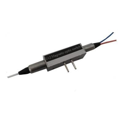
A fast optical switch can still be the wrong purchase when its driver has not been defined. For equipment developers evaluating a 1×2 magneto optical switch supplier, Feiyi’s 1×2 magneto-optical switch provides a starting point for 1520–1580 nm protection, monitoring and measurement paths. Before ordering a sample, resolve the electrical pulse specification, the common-port route and the required state after power loss. The published optical switching time alone does not answer those integration questions.
The device is a compact component rather than a complete rack controller. Its catalog combines optical performance, a pulse-drive diagram and a broad ordering matrix. Those three kinds of information need to agree for the actual configuration. An instrument team can use the dimensions and optical limits to screen the component, but should obtain an approved electrical drawing before connecting a production driver.
A 1×2 magneto optical switch supplier should define the complete drive event
Feiyi lists a 5 V switch-power entry and a pulse-duration row of 0.2 ms minimum, 0.3 ms typical and 0.5 ms maximum. The separate row with the conflicting voltage label and current unit prevents those entries from becoming a complete electrical design specification. The buyer needs the agreed drive amplitude, current requirement, pulse duration, polarity and permissible repetition behavior for the ordered version.
Opposite 5 V pulses select the Port 2 and Port 3 routes
The pin table associates Port 1→Port 2 with Pin 1 at ground and a 5 V pulse on Pin 2. It associates Port 1→Port 3 with a 5 V pulse on Pin 1 and Pin 2 at ground. This is a directional pulse description, not permission to apply an arbitrary continuous voltage between the pins. Confirm the pin identification on the supplied mechanical drawing, including which view defines it.
An OEM replacing a board-controlled optical branch may already have a driver intended for a different switch. Matching a nominal 5 V value is insufficient. That board may use a held logic level, a different pulse polarity or another current capability. Compare the entire drive event before reusing it. A connector that physically fits does not establish electrical interchangeability.
For the sample fixture, label the electrical pins separately from the optical ports. Exercise the two permitted drive directions with the agreed pulse conditions, and observe which output carries light after each event. A useful record associates the electrical event with a measured optical route; writing only “switch passed” loses the information needed to reproduce the result on the equipment board.
Also decide what the controller should do if a selection command is interrupted. The catalog pin table does not define behavior during a partially delivered pulse, a driver reset or an unexpected supply interruption. Establish the application’s recovery procedure with the approved device information. If the controller requires positive confirmation of the selected optical route, define how the instrument obtains that confirmation rather than assuming that issuing the command proves the result.
The optical response below 200 µs is different from pulse duration
The optical table specifies a switch time below 200 µs, while the electrical pulse-duration row is expressed in milliseconds. These entries describe different parts of the operation and should not be substituted for one another. Obtain the definition of the optical timing measurement: its trigger, the observation point and the condition that counts as a stable selected path.
For a protection controller, total interruption also includes fault detection, the decision to switch and the receiving equipment’s response. A component specification does not certify that complete sequence. Record the component timing and the system timing separately during sample qualification. This keeps an acceptable optical device from being blamed for a delay introduced elsewhere in the controller.
Latching behavior must be agreed for startup and power loss
The product lists latching and non-latching choices. Identify the supplied choice and the expected route before the first pulse, after a valid selection and after drive power disappears. For a latching implementation, retaining a state and knowing that state are separate requirements. The controller may need an initialization procedure when it cannot determine the previous route.
As a general technical reference, Agiltron’s magneto-optical switch documentation describes electrically controlled solid-state switching and latching operation. Its explanation is useful background; its device ratings and drive conditions do not define the Feiyi component being purchased.
Qualify the 1520–1580 nm magneto-optical path before accepting other ordering options
The clear optical specification on Feiyi’s page covers 1520–1580 nm. The ordering matrix contains additional wavelength and fiber choices, but their presence does not prove that every choice has the same insertion loss, isolation or switching performance. Tie the sample and subsequent order to a configuration-specific specification, particularly when the application falls outside the stated optical table.
A fiber-sensing instrument operating within this band can begin with the listed ≤1.0 dB insertion loss, ≥40 dB crosstalk figure and ≥50 dB return loss. The source, receiver and any connected components still determine whether those limits fit the instrument. Reserve loss for connectors and external leads instead of assigning the full available path budget to the switch.
| Published optical entry | Question for the sample program |
|---|---|
| PDL ≤0.2 dB, typical 0.1 dB | Does the instrument tolerate the specified polarization-dependent variation? |
| Repeatability ±0.01 dB | Can repeated route measurements reproduce the approved test condition? |
| Transmission power ≤500 mW | Is the actual source condition covered, including any pulsed operation? |
| Operating temperature −20 to +75°C | What temperature will the component experience inside the enclosure? |
These are catalog limits, not measurements performed on the buyer’s sample. Agree the wavelength, connector inclusion and optical reference arrangement used for acceptance. The return-loss result is particularly sensitive to the actual interface and its condition. A receiving test should be able to distinguish a dirty external connection from a problem inside the switching path.
Low PDL does not establish a polarization-maintaining switch
The published PDL entry describes variation in loss with polarization. It does not establish polarization-maintaining fiber, axis alignment or an extinction-ratio specification. A coherent or polarization-sensitive system should not approve this device as a PM switch solely because its PDL is small. Obtain the needed polarization behavior directly for the intended configuration.
The same caution applies to the broad fiber choices in the ordering matrix. Single-mode and multimode options are not interchangeable optical interfaces. If a design team requests a wavelength or fiber combination different from the 1520–1580 nm specification, its review should begin with the approved data for that version rather than with copied limits from this table.

Use the 28.6 mm package drawing to test cable and board clearances
The listed outline is 28.6 × 7.6 × 8.5 mm. A small body can fit a board space while its fiber exits remain difficult to route. Review the drawing with the actual mounting surface, connector access and cable restraint. Allow the optical leads to reach their interfaces without using the switch body as a cable anchor.
Consider a monitoring instrument with two output fibers leaving opposite sides of a narrow enclosure. Its service cover may press against the leads even though the component itself has adequate clearance. A sample installation should reproduce the intended cover and retention arrangement. Compare the selected path before and after assembly so that a mounting-induced change is visible before the enclosure design is released.
Feiyi’s ordering choices include bare fiber and a 900 µm tube, with several connector and fiber-length entries. State the selected protection, connector polish and length in the approved configuration. A photograph of a loose component cannot settle those choices. Keep the assembly drawing and order description consistent, especially if the leads will be spliced into the equipment.
The supplier documentation should also identify the pin view and route labels used on the delivered device. A board designer and a receiving technician can read the same drawing from different orientations. Agreeing the view before assembly prevents a wiring reversal from becoming an unexplained optical-state failure.
Mechanical and instrument switches answer different equipment requirements
The 1×2 mechanical optical switch offers another component route to investigate when the design permits its switching mechanism and timing. It should be evaluated against its own optical table and drive arrangement. The magneto-optical device’s pulse diagram is not a generic driver specification for every two-way switch.
For an 850 nm multimode application, Feiyi’s 1×2 FSW OSW 850 nm module is a more relevant initial comparison than importing the 1520–1580 nm magneto-optical limits. Its housed module interface and control requirements also change the integration task. The decision is partly about the required wavelength and partly about whether the buyer wants a component or an instrument module.
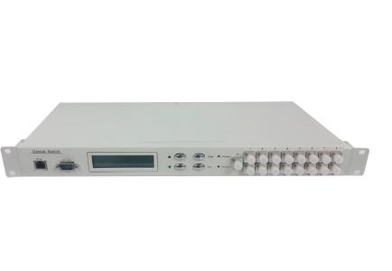
The FSW-1U-1X10-MM-FCPC rack instrument addresses multiple routes with an instrument control interface. It is not a direct replacement for a compact two-route component. A laboratory selecting a complete switching instrument should evaluate channel count, commands and rack connections, while an embedded-equipment developer must resolve the component driver.
Feiyi’s magneto-optic and mechanical switch comparison discusses the technology choice more broadly. For this purchase, make the narrower decision: which device can meet the approved optical route, driver and state behavior in the actual enclosure?
Release the magneto-optical order with a traceable pulse and route definition
A sample approval should leave behind three connected records: the ordered component configuration, the permitted electrical drive event and the observed Port 1→Port 2/Port 3 behavior. Identify any unresolved catalog row before approval. Do not let a purchasing shorthand such as “5 V fast switch” replace the document that the board designer used.
For repeated orders, preserve the selected latching option and fiber termination with the supplier’s agreed configuration identifier. If the driver or fiber arrangement changes, decide whether another sample review is needed. A component with the same external dimensions can still require a different electrical or optical approval.
Arrange shipment protection around the actual fiber exits and pins. Request labeling that lets receiving staff identify the configured switch before connecting it to a driver. The product page does not establish a standard shipping kit, ready stock or a guaranteed lead time; those details should be agreed for the order rather than assumed from the component’s size.
Purchase the sample once the conflicting drive units are resolved and the port-state sequence is documented. Then qualify it with the source, driver and enclosure it will actually use. If those conditions are still undecided, the next useful document is the approved electrical and mechanical drawing—not a faster headline switching number.