PM 980nm Fiber Coupler Supplier: Choose the Tap Ratio From the Monitor Branch
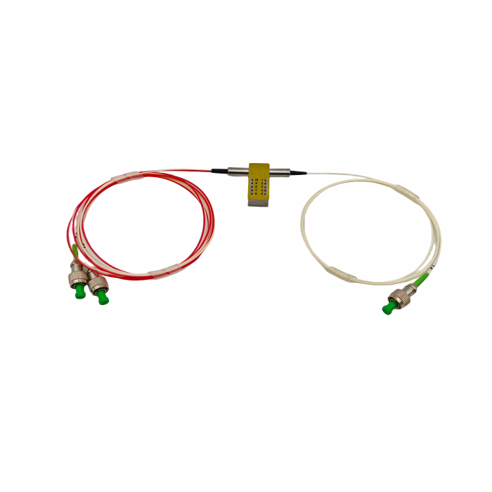
A PM 980nm fiber coupler supplier should not be asked for “a small tap” without being told what the tapped light will measure. Feiyi’s PM 980/1030/1064nm Coupler supports coupling ratios from 1% to 50%, 1×2 and 2×2 layouts, PM980/PM1060 fibers and several package styles. At 980 nm, a buyer may be sampling pump power, feeding a reference detector, balancing a sensor path or dividing light between two functional branches. Each job points to a different ratio and acceptance method.
The practical starting point is the detector or secondary branch: how much optical power does it actually need, and how much can the main path afford to lose? A 1% monitor tap preserves far more power in the through path than a 50/50 split. A 20/80 or 30/70 coupler belongs to another system balance. The supplier can build against the requirement only when the buyer states the intended ratio, port identity, PM fiber and environment together.
A PM 980nm fiber coupler supplier should receive the detector requirement before a tap ratio
Suppose a pump-monitor photodiode needs only a small sample to verify that a 980 nm source is active. A 50/50 coupler can waste half the launched power before the signal reaches the main optical job. In that case, a 1/99, 2/98 or 5/95 style split may be more appropriate, provided the detector still receives enough level across the source’s operating range.
Now consider a sensor architecture that compares two channels with similar optical levels. A near-equal split may be intentional. The supplier cannot infer which situation applies from the wavelength. The purchase file should state the optical function of both outputs and the minimum/maximum useful level at the secondary branch.
The low-power tap should be identified by port, not by cable position
Asymmetric couplers can be miswired if an assembler assumes the left or top lead is always the tap. Put the through and tap port names on the drawing and preserve those labels through receiving. A ratio test should confirm which physical pigtail carries the low-power branch before the leads are routed into a crowded module.
For a service replacement, photograph or record the old port labels before disconnection. A correct 5/95 coupler connected backward can create a system failure that looks like a wrong coupling ratio.
Feiyi’s ratio table shows why branch insertion loss must follow the ordered split
The Feiyi table lists P-grade branch losses of 6.8/6.8 dB for 50/50, 7.4/1.1 dB for 20/80, 10.8/0.6 dB for 10/90, 14.2/0.4 dB for 5/95, 18.5/0.2 dB for 2/98 and 21.0/0.2 dB for 1/99. These values make sense only when the high- and low-power branches are identified. The large number on a 1% branch is the consequence of intentionally sending very little power there.
A buyer should therefore resist a generic specification such as “insertion loss below 1 dB on all ports.” That would contradict the purpose of an asymmetric tap. Instead, define the allowed through-path loss, the expected tap ratio and any tolerance that matters to the detector or calibration model.
Excess loss is the better place to look for unwanted loss beyond the intended split
Feiyi lists typical excess loss of 0.07 dB for P grade and 0.1 dB for A grade. This metric helps separate the coupler’s unavoidable power division from additional loss introduced by the component. Keep it on a different inspection line from branch insertion loss so an intentionally weak tap is not mistaken for excess optical loss.
DK Photonics’ PM tap-coupler documentation provides useful external context by treating coupling ratio, port configuration, extinction ratio, fiber and power handling as separate order variables. Its numerical specifications are not Feiyi specifications; the relevance is the purchasing logic.
PM980 fiber should be the default discussion point for a 980 nm monitoring branch
The Feiyi coupler family lists PM980 and PM1060 fiber. For a 980 nm source chain, PM980 is the natural interface to review first, but the actual adjoining fiber should still be confirmed. If a module contains a deliberate PM980-to-PM1060 transition, engineering should own that transition and axis alignment rather than leaving the supplier to infer it from the product family.
When a monitor tap feeds a detector through a splice, include the tap-port fiber type and protection style in the drawing. When it feeds a removable instrument, the connector and axis reference become part of the interface. The same coupling ratio can behave correctly in one assembly and create avoidable loss in another if the fiber handoff is poorly defined.
A PM coupler should preserve the axis convention used by the pump or sensor system
Feiyi lists a minimum extinction-ratio line in its performance table and promotes the device for polarization-maintaining applications. The order should identify the intended PM axis and the physical reference used at connectors or splices. The buyer should not assume that “PM980” alone communicates the launch orientation.
1×2 and 2×2 layouts serve different monitoring and distribution architectures
A 1×2 coupler is straightforward when one source is divided into a main path and one monitor path. A 2×2 configuration can be useful when the system needs two input/output relationships, but that extra topology needs a clear port map. Do not order 2×2 “for flexibility” without identifying how all four pigtails will be used; unused or misidentified ports complicate service and acceptance.
For an OEM using 2×2, preserve port labels through the mechanical assembly and verify the intended branch relationship before the leads are bundled. A continuity test performed after final routing is possible, but it is cheaper to prevent ambiguous port identity before the fibers disappear into a harness.
Three 980 nm buyer scenarios lead to three different ratio decisions
Pump monitor: preserve most power in the through path and allocate only enough tap power for the detector. Balanced sensor channels: consider a more even split when both paths carry useful measurements. Reference/calibration branch: select a ratio that keeps the detector within its useful range across source variation, not merely at nominal power.
Package choice should follow the fiber protection needed at the installation point
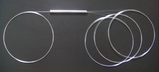
Feiyi offers Package D at 3 × 45 mm, E at 3 × 54 mm, F at 3 × 60 mm and Package G at 10 × 20 × 90 mm. The smaller D/E packages use 250 µm bare fiber, F can use bare fiber or 900 µm loose tube, and G can accommodate larger cable or loose tube. A compact pump module may accept bare fiber, while a field instrument may benefit from more protected leads.
Do not choose the smallest package if it forces sharp bends or leaves a fragile bare-fiber section exposed during service. The installed envelope includes pigtail exit, splice tray or connector service loop, not just the coupler body.
Temperature qualification should focus on the ratio needed by the monitor function
Feiyi lists operation and storage from -20 to +80 °C for this coupler family. A pump monitor inside a temperature-controlled laser may see a narrow range, while a sensor node or outdoor enclosure can see much more. If the tap drives a calibrated detector, define the environmental range over which the ratio must remain useful.
A practical acceptance test does not need to invent a new specification. It should use the product’s stated environment and the buyer’s detector requirement to decide what must be verified. If the detector calibration is sensitive to the ratio, record the ratio at the relevant conditions under a consistent launch state.
P and A grades should not be mixed in distributor stock without a visible identifier
Feiyi lists different typical excess loss and polarization sensitivity for P and A grades. A distributor should keep grade in the SKU alongside wavelength and ratio. If a customer’s approved sample is P grade, substituting A grade requires review even when the two parts share package, connector and nominal split.
980 nm couplers, VOAs, isolators and circulators belong to different control points in the same optical chain
Feiyi’s PM 980nm VOA changes optical attenuation. The PM 980nm High-Power Isolator suppresses backward light. The PM 980nm Circulator routes returned light to another port. The PM 980nm Polarization Beam Combiner/Splitter handles polarization channels. A PM fiber coupler’s role is power division by a chosen ratio.
A good bill of materials writes those functions next to the part numbers. That prevents a purchasing substitution based only on “980 nm PM component” and gives the supplier enough context to catch a mismatched request.
Receiving a 980 nm tap should reproduce the detector reference used during design
If the tap feeds a calibrated photodiode, incoming inspection should measure the coupler with a source and detector arrangement that can be related to the original design reference. The goal is not to recreate every detail of the finished instrument; it is to avoid changing the measurement setup so much that connector loss or detector scaling is confused with the coupler ratio. Record the through and tap powers under the same launch condition and calculate the relationship expected by the approved item.
For a first article sample, keep the raw readings and the port identity. Those records become useful when a later batch appears slightly different. The buyer can determine whether the difference belongs to the coupler, a changed connector condition or the measurement setup instead of relying on memory of what the first unit “looked like.”
A supplier substitution should preserve the ratio tolerance that matters to the detector
A replacement may have the same nominal 10/90 or 5/95 label but a different allowed ratio tolerance. If the monitor detector has comfortable dynamic range, that difference may be acceptable; if the detector is used for closed-loop power control, it may not be. Put the functional tolerance in the engineering record so procurement can judge a substitute against the instrument requirement rather than against a product name.
The same logic applies when the source power is changed. A higher source can drive the monitor detector closer to saturation even when the ratio is unchanged. Review the detector range and tap ratio together before carrying an old coupler into a redesigned pump module.
Custom 980 nm builds should keep requested options in one configuration line
Feiyi’s family supports custom coupling ratios and several fiber, connector, length and package choices. When more than one option is customized, combine them into one controlled configuration rather than distributing the details across emails. A useful description could identify 980 nm, 1×2, the requested tap ratio, P grade, PM980 fiber, Package F, 900 µm loose tube, chosen connector polish and finished pigtail length.
That format gives the supplier a buildable definition and gives receiving a checklist tied to the optical function. It also prevents a repeat order from preserving the split ratio while accidentally changing a pigtail or package option that mattered to the installed sensor.
A repeat 980 nm coupler order should preserve what the detector was calibrated against
Once the monitor or sensor branch is calibrated, retain the coupling ratio, port identities, 1×2/2×2 configuration, P/A grade, PM fiber, package, pigtail protection, connector polish and finished length as one item definition. If the detector model or source power changes, review the ratio rather than assuming the old tap remains appropriate.
Feiyi’s unequal PM coupler article is useful when comparing asymmetric ratios, and the product page provides the actual Feiyi ratio table and package options. The supplier handoff should be simple enough to read in one place: 980 nm, ratio, through/tap ports, detector purpose, fiber, grade, package and connectors.