Single Mode Fiber Collimator Supplier: Replacing a 200 mm Free-Space Interface
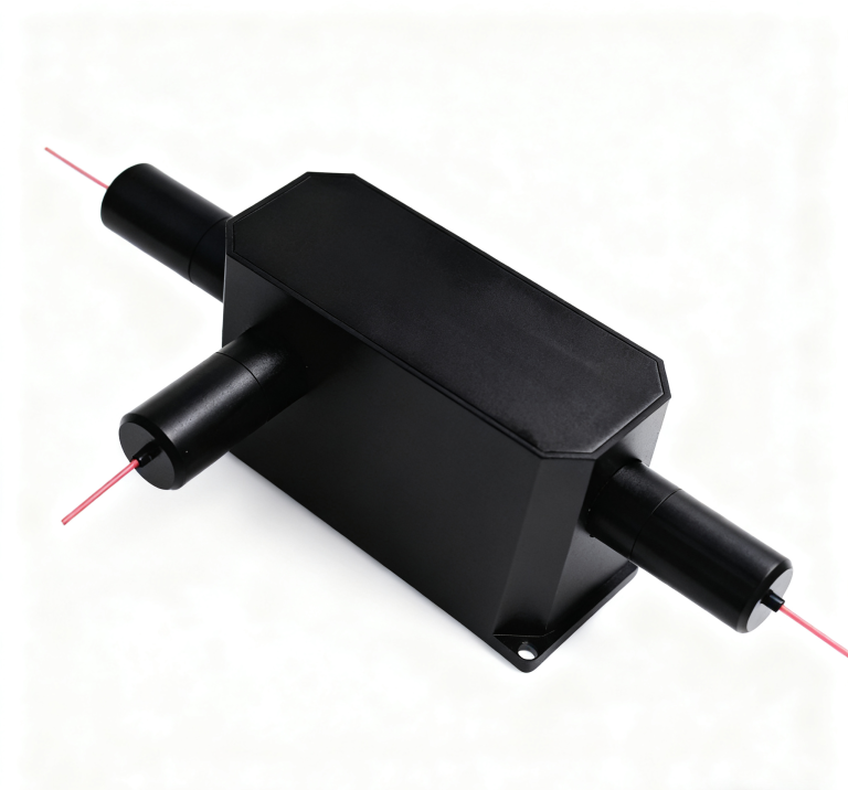
A replacement collimator fits the sleeve, but the receiver no longer couples as it did before. For a maintenance buyer approaching a single mode fiber collimator supplier, this is a reason to recover the original optical interface, not immediately request a lower loss number. Feiyi’s single-mode collimator with WD 200 mm lists 1310/1550 nm operation and G657A1 fiber. Start there when the equipment uses a matching single-mode free-space path, and confirm the distance datum, termination and receiving optics before approving the spare.
The replacement task belongs to instrument builders, optical equipment service teams and buyers maintaining repeat assemblies. It differs from choosing the first collimator for a new design: the installed holder, receiving aperture and source usually already exist. The useful purchasing document describes the behavior that must survive the replacement, along with the interfaces that cannot change.
Recover the single-mode optical interface before measuring the spare
The old assembly establishes clues about the intended interface, but it should not become the sole acceptance reference if it is damaged or contaminated. Begin with the equipment drawing and approved configuration. Recover the operating wavelength, fiber type, lens location, connector and free-space gap. Then identify which observations from the old assembly are trustworthy enough to compare.
A 200 mm distance needs the old lens and receiver datums
The Feiyi product names a 200 mm working distance. That description does not tell a service technician which face of an existing holder was used as the original distance reference. Locate the lens position and the relevant receiving surface on the installed drawing. Include windows or intermediate optics that remain between them after the replacement.
A service team may have access only to the front of a sealed optical head. In that situation, the visible housing end is not automatically the lens datum. Approving a spare by measuring from the accessible metal surface can shift the receiving plane while preserving the apparent gap. Ask for a dimensional reference that can be related to the equipment’s actual mounting features.
If the receiver has an adjustable position, record its intended setting before removing the old component. A large adjustment made to accommodate the new sample may conceal an interface difference that the next production unit cannot tolerate. Decide whether the purchase is a compatible replacement or a redesign requiring a revised alignment procedure.
G657A1 fiber should remain visible in the replacement description
The dedicated WD 200 mm single-mode listing specifies G657A1 fiber. Retain that designation in the replacement request rather than shortening the description to “single-mode.” If a proposed alternative uses another fiber, the supplier should identify the configuration and its optical validation, so the buyer can decide whether a new approval is needed.
The fiber route also belongs in the interface record. Feiyi lists a 2.2 ± 0.1 m pigtail for this product. Establish the useful length between the optical body and the termination, and identify where the installed equipment stores any spare length. A lead that is pulled tight during servicing can load the small housing even when its nominal length appears adequate.
Compare single mode fiber collimator loss at the same reference planes
Feiyi gives an insertion-loss limit of 0.25 dB and return loss of at least 55 dB for the listed single-mode WD 200 mm product. The measurement note specifies 25°C and excludes connectors. These conditions are central to a replacement comparison: an equipment path containing extra leads and mating interfaces should not be judged as if it were the bare component.
A buyer may initially compare the old and new assemblies using whichever patch leads are already on the workbench. That approach can produce an apparent improvement or deterioration unrelated to the collimator. Preserve the same source, connections, receiving geometry and reference procedure when the purpose is to isolate the replacement component’s behavior.
1310 nm and 1550 nm samples should not share an unexplained loss result
Write the actual equipment wavelength beside every measurement. If the spare is intended for 1550 nm, a transmission check at 1310 nm can answer a different question from the one the purchase must resolve. Likewise, a qualification covering both wavelengths needs an explicit result at each required condition, rather than a single unlabeled number.
Do not assume that a measurement of total emitted power predicts the power coupled into a receiving fiber. The receiver’s aperture, alignment and optical arrangement determine what is collected. A system-level comparison should therefore identify the receiving element and the quantity being measured, while the component comparison retains its agreed intrinsic boundary.
The Thorlabs discussion of single-mode collimation explains why wavelength and the guided field influence propagation. That general relationship supports a wavelength-specific approval; another manufacturer’s focal lengths, beam diameters and simulations do not establish the performance of the Feiyi assembly.
Return loss deserves a separate record from insertion loss. A replacement can pass a forward transmission check while the installed optical environment reflects differently toward the source. Keep the receiving optics, target or downstream termination defined when investigating that behavior. The catalog return-loss entry should not be extended into an unsupported promise about the complete serviced instrument.
If the old sample’s loss has increased over time, retain a clean reference connection during diagnosis. A photograph of the original mounting position and the approved receiver setting can distinguish a service-related displacement from a change in the delivered assembly. Keep the observation specific: describe what moved, what was cleaned and which wavelength was measured. Avoid labeling every difference as collimator aging when the original reference plane or mating connection has not been recovered.

The 2.4 × 14 mm collimator body is only one compatibility check
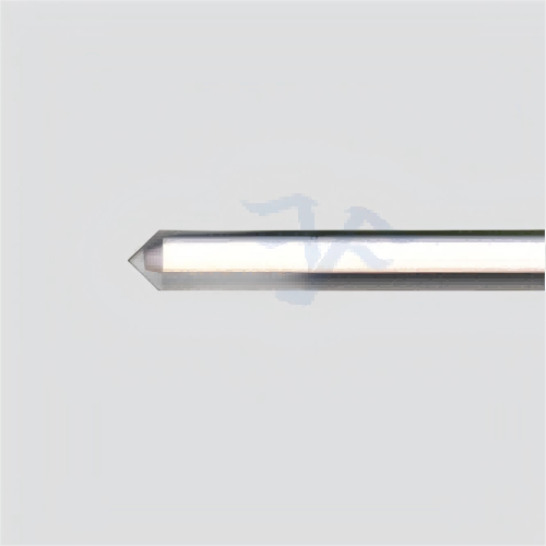
The listed body dimensions help assess whether the assembly can enter the equipment holder. They do not establish that the lens is in the same location, that the holder contacts the same surface or that the pigtail leaves the mount without strain. Recover those relationships before deciding a visually similar component is interchangeable.
For an OEM keeping a service spare alongside production parts, the mounting engagement should be recorded as part of the approved configuration. Identify the section of the cylindrical body that is retained and the clearance around its lens end. If the original attachment used an adhesive, the replacement procedure should specify the approved assembly process rather than letting the maintenance bench improvise one.
FC/PC and FC/APC termination choices change the service interface
The ordering information provides connector choices, including no connector, FC/PC and FC/APC. Select the termination used by the equipment and identify the mating port. An angled and a physical-contact connector should not be substituted on the assumption that the same connector family name guarantees a suitable connection.
For a bare-fiber assembly, describe the downstream joining arrangement and where receiving inspection ends. If the buyer adds the final termination, its process should not be represented as part of the supplier’s delivered loss result. If the supplier delivers the terminated pigtail, record that interface with the approved sample so future orders retain the same boundary.
During packing and storage, the important objects are the lens face, the small body and the pigtail termination. Agree how each is protected and identified. A protective cap should be removable without pulling the fiber, and any temporary support should not be mistaken for an installed component. These are proposed order requirements, not a claim of a standard packing or dispatch method.
Keep the single-mode spare separate from nearby collimator families
Several Feiyi products can appear relevant when the original item is described simply as a fiber collimator. Comparing them is useful only if the buyer also identifies the change each alternative makes to the equipment.
The coaxial collimator lists a 5–10 mm working distance and a 2.5 × 10 mm body. It belongs in a short optical-head design discussion. Its compact size does not make it a compatible spare for the dedicated 200 mm assembly, even if an adapter can be made to hold it.
The multimode WD 200 mm version lists 50/125 fiber and 850/1310 nm operation. A shared working distance does not preserve the single-mode input field or the receiving conditions. Consider it only when the optical channel itself is being changed to a multimode arrangement and the system can be requalified.
The general single-fiber collimator is a useful route for discussing a different configured lens, working distance or termination. It can support a deliberate redesign, but it should not be approved as an unnamed substitute for the dedicated single-mode product. Record the selected construction and require a drawing that resolves the original interface requirements.
Polarization adds another boundary. An ordinary single-mode order does not establish maintenance of a particular polarization axis. Where the serviced instrument depends on that behavior, use the separate PM collimator interface discussion to define the axis requirement before choosing the replacement family. Avoid adding a PM guarantee to a part whose listing does not supply it.
Approve the mounted replacement without hiding a redesign
First measure the candidate under the recovered optical conditions outside the final mount, where possible. Then install it using the equipment’s intended retention and pigtail route. Repeat the receiving-plane observation and the agreed transmission check. If the optical result changes after mounting, investigate the holder and assembly process before requesting a different loss grade.
The catalog’s 0.5 W power entry and −20 to +75°C operating range remain conditions to review against the actual application. A source with pulses, an enclosure with local heating or an unusual thermal exposure requires its own engineering assessment. The replacement purchase should not acquire a peak-power rating or environmental qualification that is absent from the approved product record.
A technician restoring one instrument may accept an alignment adjustment that an OEM producing many units cannot repeat. Keep those two approval situations distinct. For a service repair, document the adjustment used and decide whether the same spare can be fitted again. For production, confirm the holder and receiving optics can reach the required result using the intended assembly method without individual redesign.
When the new part works only after changing the receiver position, termination or source conditions, name that change explicitly. It can be a valid engineering choice, but it creates a revised configuration. The purchasing team should then replace the old description and retain the revised acceptance boundary, rather than carrying both arrangements under one supposedly interchangeable item.
Release the spare order with a drawing that connects the 200 mm optical gap to the 2.4 × 14 mm mounting body, identifies the selected 1310 or 1550 nm configuration and preserves the actual termination. That record gives the next replacement a usable starting point. A lower loss figure on an unrelated configuration cannot do the same job.