PM 2000nm Circulator Manufacturer: Freeze the 2 Micron Optical Path Before Ordering
A 2 µm optical system usually reaches the circulator after the source, fiber and detector architecture have already been chosen. That makes a PM 2000nm circulator manufacturer decision less about finding a familiar three-port part and more about preserving the optical conditions the rest of the instrument expects. For Feiyi’s PM 2000nm Circulator, the first items to freeze are the 2000 ± 30 nm center band, Port 1 → Port 2 → Port 3 routing, PM1950 fiber, working axis, optical power level and connector interface. The listed product is relevant to optical amplifiers, fiber sensors, fiber instruments, dispersion-compensation arrangements and bidirectional optical links.
For a buyer building a thulium-band source, a 2 µm sensing bench or a polarization-sensitive instrument, the practical mistake is to start with FC/APC versus FC/PC and leave the optical path for later. Connector type can be changed in the ordering configuration; wavelength, port direction, polarization behavior and power limit determine whether the component belongs in the system at all. Feiyi also lists PM 1950nm and shorter-wavelength PM circulators, so the purchase file should name the actual operating band rather than simply say “2 micron circulator.”
A PM 2000nm circulator manufacturer order begins at 2000 ± 30 nm, not at the connector
Feiyi’s PM 2000nm product page specifies a 2000 ± 30 nm center wavelength. That range is the useful starting point for the component under the stated product conditions; it should not be turned into a promise about an arbitrary source spectrum. A procurement drawing should show the source center wavelength, expected drift or tuning range and the wavelength at which the buyer expects acceptance measurements to be made. If the application deliberately moves outside the listed band, that becomes a new technical question rather than a connector option.
The product identifies PM1950 as the fiber model. This choice is consistent with the broader 2 µm PM-fiber ecosystem: Coherent’s PM1950 fiber information, for example, describes a polarization-maintaining fiber optimized across 1850–2200 nm and cites 2 µm component pigtailing and thulium-fiber laser/amplifier work as typical applications. That external information is useful industry context; Feiyi’s own acceptance values must still come from the Feiyi product specification rather than from another fiber or component vendor.
PM1950 fiber should remain attached to the axis requirement in the purchase file
Feiyi lists both fast-axis and slow-axis working options and a minimum extinction ratio of at least 18 dB for this circulator. A buyer should therefore identify which axis is intended to carry the launched polarization and how that axis will be referenced at each termination. “PM fiber” by itself does not document the launch condition. If a connector key is used as an assembly reference, the drawing should state the required relationship between that key and the PM axis instead of assuming every supplier uses the same convention.
A distributor stocking 2 µm components should also avoid treating PM1950 as a cosmetic pigtail choice. Replacing it with an unconfirmed fiber changes the optical interface that the buyer originally approved. For a repeat order, retain the fiber type, jacket form, length and axis instruction as part of the item identity.
Insertion loss and isolation describe different risks on a 2 µm return path
The Feiyi PM 2000nm Circulator lists 1.2 dB typical insertion loss and 1.5 dB maximum insertion loss, together with typical isolation of at least 25 dB and minimum isolation of at least 20 dB. These numbers should not be blended into one general “low-loss, high-isolation” approval. Insertion loss tells the designer how much wanted light is lost through the routed path. Isolation addresses unwanted propagation toward a port that should be protected from the reverse path.
Consider a fiber sensor in which launched light leaves Port 1 through Port 2 and the returning measurement is expected at Port 3. The source-side power budget cares about loss through the forward route, while the source-protection question cares about how effectively returning light is prevented from reaching the wrong port. A buyer who checks only insertion loss can approve a part without ever documenting the reverse-path requirement. A buyer who checks only isolation may overlook a power budget that is already tight after other 2 µm components are added.
Return loss, crosstalk and extinction ratio should stay as separate acceptance lines
The same Feiyi page lists return loss of at least 50 dB, crosstalk of at least 50 dB, polarization-dependent loss no greater than 0.15 dB and a minimum extinction ratio of at least 18 dB. Each value addresses a different behavior. Return loss concerns reflected power at an interface; crosstalk concerns unwanted coupling between routed paths; extinction ratio concerns polarization quality; PDL describes loss variation with polarization state. A single optical-power reading cannot substitute for all four.
For an engineering handoff, it is more useful to put these as separate rows in the acceptance file than to write “high performance.” That lets purchasing, incoming inspection and the optical engineer refer to the same conditions when the second batch arrives.
Port 1 → Port 2 → Port 3 routing should be frozen before comparing three-port and four-port circulators
The PM 2000nm product is specified as a three-port route: Port 1 to Port 2 to Port 3. Feiyi also sells a separate 4 Port Optical Circulator in its non-PM circulator family. The four-port product extends routing so light can continue from the third port toward a fourth port. That can support more complex add/drop, mux/demux or bidirectional layouts, but it is not automatically a better replacement for a three-port PM device.

A fourth port is useful only when the optical route actually needs it
An instrument designer replacing a three-port return-path component should not add a fourth port merely because a four-port circulator exists elsewhere in the catalog. The additional interface changes routing, packaging and documentation. Conversely, a project that genuinely needs another directional handoff should not try to emulate it by joining extra splitters around a three-port device without rechecking loss and polarization behavior.
The buyer’s drawing should therefore show arrows between ports, not just connector labels. This is especially important when two teams use different port numbering conventions in block diagrams. A simple route sketch eliminates ambiguity before production.
The listed 300 mW power handling is a boundary, not a generic 2 µm power class
Feiyi lists maximum power handling of 300 mW for the PM 2000nm Circulator. Use that number for the listed product rather than importing a higher power rating from another 2 µm circulator found in the market. Industry suppliers do offer high-power 2 µm circulators, and published external datasheets may show multi-watt classes, but those figures belong to those specific designs and do not increase the rating of Feiyi’s listed 300 mW configuration.
This distinction matters in thulium-fiber laser and amplifier work. An engineering prototype may operate comfortably below 300 mW during alignment and later be upgraded to a higher source level. The purchasing record should reflect the intended delivered power, not the prototype’s temporary operating point. If a planned system can exceed the listed limit, treat it as a separate technical qualification question before ordering.
Peak power also deserves separate attention in pulsed systems. The Feiyi page gives an average maximum power value but does not publish a pulse-duration or peak-power specification for this product. A pulsed 2 µm project should therefore provide pulse width, repetition rate and expected peak level for review instead of inferring pulse capability from the average-power line.
FC/PC, FC/APC and bare-fiber options change the delivered interface
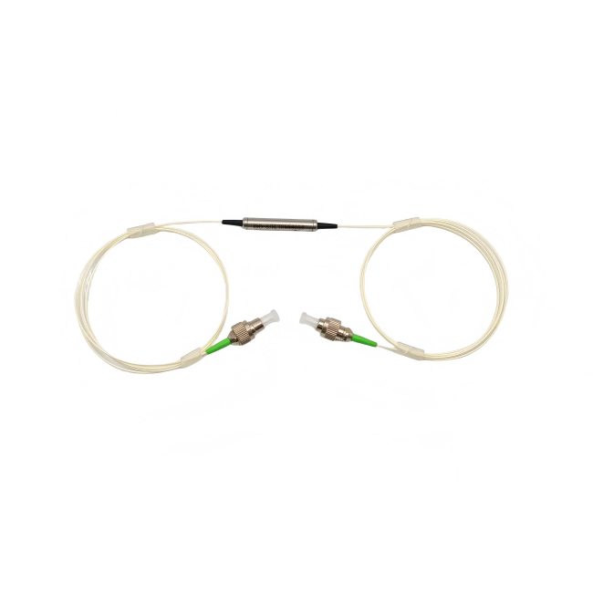
The ordering information lists bare fiber and PM1950 fiber choices, FC/PC, FC/APC, SC/PC and SC/APC connector styles, and example fiber lengths of 0.5 m, 1 m and 2 m. These options belong in the part definition. A lab buyer who approves an FC/APC prototype should not allow a later FC/PC substitution simply because both are FC housings. The end-face geometry and reflection behavior are different, and the mating adapter must match the selected polish.
A system integrator may deliberately choose bare fiber when the circulator will be spliced inside a module. In that case, the splice process and axis alignment become part of the integration plan. A field-replaceable instrument may prefer connectors for serviceability, accepting the additional interfaces. Neither choice is universally superior; the correct one follows the module architecture.
Fiber length should be treated as an optical-mechanical interface, not spare slack
When 0.5 m, 1 m or 2 m pigtails are considered, the buyer should check the actual enclosure route, bend management and splice or connector location. Extra fiber can simplify assembly but also creates additional routing space inside a compact instrument. A very short pigtail may reduce slack but leave no service loop. Specify the required finished length and jacket arrangement for the mechanical drawing rather than leaving “standard length” undefined.
The package choice belongs in the same handoff as the operating temperature
Feiyi lists cylindrical packages of Φ5.5 × L35 mm and Φ5.5 × L50 mm, plus an ABS-box option of 90 × 20 × 10 mm. The operating temperature range is −10 to +75 °C and the storage range is −40 to +85 °C. These dimensions and temperature limits should be checked together with the instrument environment. A package that fits a bench fixture may not fit the final enclosure once fiber exit direction and bend space are included.
A manufacturer qualification should therefore use the selected package, pigtail and connector configuration, not an idealized bare component. For incoming inspection, confirm the body style and optical interface match the approved drawing before interpreting a measurement result from the wrong physical variant.
| Feiyi PM 2000nm item | Published value or option | What the buyer should freeze |
|---|---|---|
| Optical band | 2000 ± 30 nm | Source range and acceptance wavelength |
| Insertion loss | 1.2 dB typical, 1.5 dB maximum | Allowed path loss under agreed test conditions |
| Isolation | ≥25 dB typical, ≥20 dB minimum | Reverse-path requirement |
| Polarization | PM1950; fast or slow working axis; ER ≥18 dB | Axis reference from source to termination |
| Power | 300 mW maximum | Actual CW level and any pulsed condition requiring review |
Nearby 2 µm components should be compared by function, not by wavelength alone
A 2000 nm label does not make several passive components interchangeable. Feiyi’s PM 2000nm VOA is for controlled attenuation, not directional routing. The product titled PM 2000nm In-Line Polarizer is for polarization selection rather than returning a signal from Port 2 toward a separate detector port. The PM 2000nm DWDM 3-Port Device performs wavelength-selective routing, which is a different optical job from a circulator’s non-reciprocal port sequence.
That distinction is useful when a buyer receives a block diagram containing several unlabeled “3-port” symbols. Each symbol should be identified by optical function before procurement. A circulator routes by direction, a WDM routes by wavelength, a VOA controls power and a polarizer controls polarization state. Matching wavelength does not remove those functional differences.
A PM 1950nm circulator is the adjacent wavelength choice, not an automatic substitute
Feiyi’s PM 1950nm Circulator is close in spectral region, but a project centered at 2000 nm should not substitute it without checking the actual source range and the 1950 nm product’s own specification. For a tunable or broadband project, write the full operating range into the engineering file so the selected part is evaluated against the spectrum that will really reach it.
A repeat order should preserve the exact optical build that passed the first acceptance
For repeat purchasing, retain the approved wavelength, PM fiber, axis, port route, connector polish, fiber length, package and acceptance limits as one configuration record. Do not identify the item only by “PM 2000nm circulator.” Two units with the same marketing name can represent different connector or pigtail builds, and those differences can matter when they return to a calibrated instrument.
If the first batch is used in a fiber sensor, keep the acceptance data tied to that installed configuration. If a later order moves to an amplifier bench or a different package, treat the change explicitly rather than assuming the old record transfers unchanged. The same discipline applies to shipping: connector faces and fiber exits should be protected so the delivered interface corresponds to the tested build, but the exact packing method should be confirmed for the order rather than invented from a generic component practice.
For broader wavelength comparison, Feiyi’s PM circulator manufacturer guide explains how wavelength, isolation and PM-axis choices interact across the family. The older PM circulator spectrum overview also shows why 780 nm through 2000 nm devices should be treated as a family of wavelength-specific builds rather than one universal component.
Before releasing a 2 µm purchase order, make the optical path readable without opening an email thread: center wavelength and range, Port 1 → 2 → 3 direction, PM1950 and working axis, maximum optical power, connector polish, fiber length and package should all be visible in the controlled item description. That is the information a manufacturer can build against and the buyer can verify again when the next batch arrives.