Fiber Optic Switch Manufacturer: Specify Route State, Latching and Drive Before Connectors
A buyer searching for a fiber optic switch manufacturer should define the required light path before discussing connectors or enclosure style. A 1×2 switch, a 2×2 switch and a rack-mounted multi-channel switch solve different routing problems even if they operate at the same wavelength. The selection also depends on latching behavior, drive voltage, switching time, crosstalk, insertion loss and what optical route should remain when power is removed.
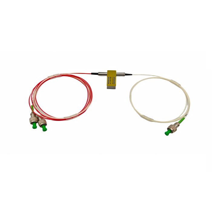
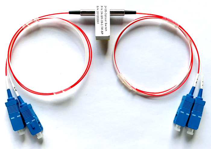
Feiyi’s published switch portfolio includes 1×1, 1×2, 1×4, 1×8, 1×10, F2x2 and rack-mounted configurations, along with polarization-maintaining switch families. For a general single-mode or multimode project, the F2x2 mechanical switch provides a useful example because its public page includes both optical and electrical specifications.
A fiber optic switch manufacturer needs the route table before the connector list
An optical switch is easiest to specify as a set of states. For a 2×2 product, draw which input connects to which output in State One and State Two. Then add wavelength, fiber, insertion-loss limit and electrical drive. This makes the requested behavior obvious to engineering, purchasing and incoming inspection.
The F2x2 mechanical switch supports two distinct 2×2 light paths
Feiyi’s F2x2 Mechanical Fiber Optic Switch is published for 850 +/-40 nm and for a single-mode range of 1260-1650 nm. The ordering information also lists common wavelengths including 1310, 1490, 1550, 1625 and 1650 nm. In the single-mode specification, typical insertion loss is 0.6 dB and maximum insertion loss is 0.8 dB.
The same page lists return loss of at least 50 dB for single mode, crosstalk of at least 70 dB, PDL no greater than 0.05 dB, wavelength-dependent loss no greater than 0.25 dB and temperature-dependent loss no greater than 0.25 dB. Those figures give a buyer measurable optical limits, but the route state still needs to be written down so the part is tested in the intended configuration.
850 nm multimode and 1260-1650 nm single-mode versions should not share one approval record
The F2x2 page publishes separate return-loss and crosstalk values for multimode and single-mode operation. The multimode version has return loss of at least 30 dB and crosstalk of at least 65 dB, while the single-mode version publishes at least 50 dB return loss and at least 70 dB crosstalk. That difference is a reminder that “F2x2 switch” is a family name rather than one universal part.
A distributor can stock both, but an OEM should keep the accepted fiber type and wavelength on the drawing. If the system is redesigned from 850 nm multimode to 1550 nm single mode, the earlier switch approval should not be carried over without review.
Fiber optic switch manufacturer selection should include latching behavior
Feiyi’s F2x2 switch supports latching and non-latching configurations. This electrical choice determines how the device behaves when drive is removed. It can be more important to system safety than a small difference in insertion loss.
Latching switches fit systems that need to preserve a selected route without continuous drive
In a latching configuration, an electrical pulse changes the route and the switch remains in that state after the drive is removed. That can be useful in optical protection, test setups or systems where power consumption and retained state matter. The controller must still generate the correct drive sequence, so the route table and pin definition should be part of the engineering handoff.
A buyer replacing a switch in an existing instrument should check the controller output before ordering. A mechanically compatible 5 V non-latching switch is not necessarily a drop-in replacement for a 5 V latching one.
Non-latching behavior can be useful when the optical path should follow the powered state
A non-latching switch changes state with applied drive and returns according to its mechanical/electrical design when drive is removed. This can be useful where the system intentionally defines a default unpowered route. The buyer should write that required default state in the specification rather than assume it from the word “non-latching.”
Feiyi’s page provides pin definitions for both modes. Those details should be compared with the control board during design review, especially if an existing cable harness is being reused.
Drive voltage and coil current belong in the switch BOM, not only the electronics drawing
Feiyi’s F2x2 ordering table supports 3 V and 5 V versions. The electrical-specification table provides different current and resistance values for latching and non-latching configurations. That means the optical part number also carries an electrical load that the controller must support.
A 3 V controller cannot be assumed compatible with a 5 V optical switch
The obvious issue is insufficient drive, but overdriving the wrong coil can also create reliability problems. Purchasing should therefore preserve the selected voltage in the exact switch description. If a controller board revision changes voltage, the switch should be included in the engineering-change review.
For distributors, voltage should be visible on shelf labels and ERP descriptions. Two 2×2 switches with the same fiber and connectors can require different drive electronics and should not be merged under one SKU.
Switching time and cycle life should be matched to how often the route changes
The F2x2 page lists switching time no greater than 8 ms and a rated lifetime of at least 10 million cycles. Those specifications matter differently across applications. A protection system may care about how quickly traffic is moved to another path, while a laboratory scanner may care about repeated cycling over a long test sequence.
A network protection path and a calibration bench place different loads on the same switch
In a protection path, the switch may remain in one state for long periods and move only during a fault or maintenance event. In a calibration bench, the device may cycle thousands of times during automated testing. The same 2×2 topology can therefore face very different lifetime demands.
The manufacturer should receive the expected switching pattern when reliability is critical. The published 10-million-cycle rating provides a baseline for the F2x2 model, but the buyer still needs to judge whether that baseline fits its own duty cycle.
Insertion loss, crosstalk and repeatability should be tested in every route that matters
Feiyi publishes F2x2 repeatability within +/-0.02 dB. A good incoming test should not measure only one favored state. Verify the optical loss in each route used by the system, then check crosstalk to the unselected path and confirm that repeated switching returns to a stable value.
Route labeling should be verified before optical numbers are interpreted
If port 3 and port 4 are swapped in a test fixture, an otherwise good switch can appear to have high loss or incorrect crosstalk. Start with the route diagram, identify the fibers physically and only then record measurements. This is especially important for bare-fiber or pigtail configurations where several leads may look identical.
Packaging and inner labels should support that same port identity. Feiyi’s public page does not publish one universal packing method, so an OEM or distributor can agree the required channel labels for its specific order.
Mechanical envelope and optical power can rule out a switch before detailed testing
Feiyi’s F2x2 page publishes a compact body size of approximately 28.0 x 12.6 x 8.0 mm and a weight of 16 g, with transmission power up to 500 mW. Those values matter when the switch sits inside an existing instrument rather than a spacious rack. A replacement part can meet the route and wavelength requirements yet still fail mechanically because the enclosure, fiber exit direction or cable bend radius no longer fits.
Retrofit projects should measure the available space and fiber exits before ordering
A service engineer replacing an older switch should record the body envelope, mounting method and direction in which fibers leave the housing. The published dimensions provide a starting point, but connector boots and pigtail routing consume additional space. Photographs are useful for context, while a dimensioned drawing is what purchasing should attach to the RFQ.
Power should be checked at the switch location in the same way. A laboratory source may be well below the 500 mW published limit, while an amplified path can approach it. If a future system revision increases source power, the switch should be included in that design review rather than assumed safe because the route topology is unchanged.
A general optical switch and a PM optical switch should be treated as separate families
Feiyi also publishes PM 1×2, PM 1×3/1×4 and PM 2×2 optical switches. Those products add polarization extinction-ratio and working-axis considerations to the route, making them appropriate when polarization must be preserved. A standard single-mode switch is sufficient when the system does not require a controlled polarization state.
PM switch specifications add axis and extinction ratio to the route table
Feiyi’s PM 1×3/1×4 switch is published for 1310/1550 nm and 780/850/980/1060 nm versions, with crosstalk of at least 55 dB, return loss of at least 50 dB, repeatability within +/-0.05 dB and a 10 ms switching time. It also publishes extinction-ratio values that the standard F2x2 switch does not need.
A buyer should move to the PM family only when the optical system needs that polarization performance. Using a PM switch in a non-polarization-sensitive link can add unnecessary specification burden, while using a standard switch in a PM chain can destroy the intended state.
Manufacturer approval should follow the exact switch topology and control mode
Once a sample is accepted, preserve the wavelength, SM/MM/PM fiber type, topology, latching mode, drive voltage, connector, fiber length and route table. If the device is customized, keep the approved pinout or drawing revision. A repeat order described only as “2×2 fiber switch” is not sufficiently controlled.
Feiyi’s F2x2 mechanical switch is the direct reference for the specifications discussed here. Buyers can also review the broader fiber optic switch range or the PM switch family. The PM switch off-state article is useful for teams designing polarization-sensitive instruments.
The best switch RFQ is a route table with optical and electrical limits attached. That gives the manufacturer an unambiguous build target and gives the buyer an incoming test that reflects the actual system instead of a generic port count.