How to Hand Off a Coupling Drawing to a Custom Lensed Fiber Supplier
For an optical engineer looking for a custom lensed fiber supplier, the most important first step is not choosing a connector or asking for a generic “lensed fiber.” The supplier needs to understand what the fiber must do at the target: the required spot shape, the working distance or target plane, the source wavelength, the fiber type, and the mechanical space around the coupling interface. Feiyi’s current lensed-fiber range includes tapered, angled, wedge, two-faceted and four-faceted geometries, so a buyer can begin with an existing geometry and then define the dimensions and optical result that need to be customized.
This approach is especially useful for teams working on laser-to-fiber or fiber-to-device coupling, beam expansion, medical illumination, and compact photonic assemblies. Before approving a custom part, identify whether the optical problem is mainly beam shaping, directional deflection, circular or ring-shaped output, or matching a small emitter or receiver. Then compare the available lensed-fiber families rather than treating every polished fiber tip as interchangeable.
A custom lensed fiber supplier needs the optical target before the mechanical drawing is frozen
A mechanical drawing can define fiber length, stripped length, connector, ferrule, and handling dimensions, but it cannot by itself explain the optical result expected from the processed tip. The useful starting point is a short optical handoff: source wavelength, source or receiver geometry, fiber type, target distance, desired spot shape, and any alignment constraints. Those items tell the supplier what the end-face geometry must accomplish.
Define the spot at the actual target plane, not at an arbitrary inspection distance
A lensed fiber is normally selected because the bare fiber’s natural divergence is not the output needed by the assembly. If the design requires a small focused spot at a chip facet, a broader spot at a detector, or a ring-shaped far field for illumination, the target plane matters. A diameter measured close to the tip cannot be assumed to describe the beam several millimeters away.
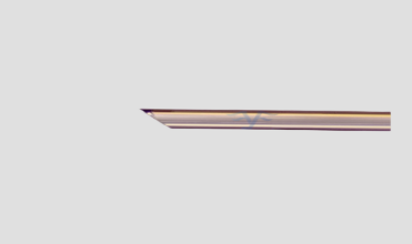
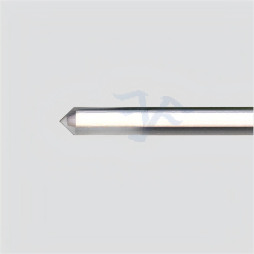
For Feiyi’s Tapered Lensed Fiber, the published customizable output includes a ring-shaped far-field spot, with an apex-angle range of 60° to 120°. That is a concrete example of why “tapered fiber” is not a complete purchase description. The apex angle is part of the optical design, and the useful result is the beam produced at the intended location.
Choose SM, MM or PM fiber from the system, not from the tip geometry
The tapered lensed-fiber page lists single-mode, multimode, polarization-maintaining and customized fiber options. The tip geometry and the fiber type solve different parts of the problem. A polarization-sensitive laser or interferometric assembly may need PM fiber because the surrounding system depends on polarization stability; an illumination path may instead favor a multimode source and different output behavior.
For a buyer, this means the fiber designation should be controlled separately from the processed-tip drawing. If the same tip geometry is later moved from an SM platform to a PM platform, it should be treated as a new optical configuration rather than a cosmetic fiber substitution.
Compare custom lensed fiber supplier options by end-face geometry and optical job
Feiyi’s lensed-fiber category is useful because it exposes several different end-face families rather than one universal product. A procurement team should compare them by the job they perform in the assembly. The table below is not a substitute for optical simulation or sample validation; it is a practical way to decide which product page deserves the first engineering discussion.
| Feiyi product family | Useful starting question | Typical decision driver |
|---|---|---|
| Tapered Lensed Fiber | Is a conical tip and ring-shaped far field part of the optical concept? | Apex angle, fiber type, target-plane beam shape |
| Angled Lensed Fiber | Does the assembly need a processed angled output rather than a straight optical axis? | Beam direction, mechanical clearance, coupling orientation |
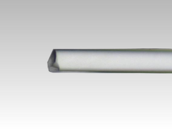
| Two-Faceted Lensed Fiber | Would a two-surface geometry better match the required beam transformation? | Facet relationship and alignment to the device |
| Four-Faceted / Pyramidal Lensed Fiber | Is a multi-facet tip required to create the intended distribution? | Facet symmetry, orientation, target illumination pattern |
| Wedge Lensed Fiber | Does the optical path require a wedge-type processed tip? | Deflection geometry and installation orientation |
A tapered lensed fiber is useful when the ring output is intentional
The Feiyi tapered product specifically publishes a ring-shaped far-field spot. That makes it a logical candidate when a ring distribution is part of the optical requirement, such as certain illumination or beam-expansion tasks. It is not automatically the right choice for a design that needs a compact Gaussian-like focus onto a small photonic feature. The buyer should state the expected beam behavior instead of assuming that “tapered” means “better coupling” in every application.
The same page also lists optional FC, LC, SC and SMA connectors with PC or APC choices. Those connector options are useful for a laboratory or modular assembly, but connector selection comes after the beam requirement. A beautifully connectorized part still fails the project if the processed tip creates the wrong field at the target.
Angled, wedge and faceted tips should be tied to an orientation datum
Any asymmetric end face creates an orientation question. If the tip must be rotated relative to a chip, detector, lens or housing feature, the drawing should define the datum used during assembly. A buyer should not rely on a photograph of a sample to communicate this relationship. The drawing can show a connector key, flat, ferrule feature, or other mechanical reference and define how the optical feature is oriented to it.
This becomes more important in repeat orders. A first sample can appear to work because a technician manually rotates the part until coupling improves. A production assembly needs a repeatable orientation that can be inspected before installation. The supplier discussion should therefore connect optical orientation to a measurable mechanical reference.
Custom lensed fiber specifications should separate the processed tip from the cable assembly
The tip, the fiber, and the connectorized assembly should be controlled as three related but separate design decisions. On its tapered lensed-fiber page, Feiyi states that fiber raw material can be selected from SM, MM, PM or customized options, and that fiber length and stripped-coating length can be customized. The page also notes direct processing of bare fiber without auxiliary adhesives and optional coating directly on the bare-fiber end face.
These details matter because a buyer may need the same optical tip in several mechanical versions. A development laboratory could use a connectorized sample, while the production module might need a bare-fiber pigtail with a defined stripped length. If the optical geometry is approved independently from the lead format, the project can control changes more clearly.
Coating belongs in the optical and environmental discussion
An optional coating on the processed end face should not be treated as a decorative addition. Coating selection depends on wavelength, optical function, and the environment around the exposed tip. Feiyi’s page confirms that coating can be applied directly to the bare-fiber end face, but it does not claim one coating is universal for every source or application. The engineering handoff should therefore state the working wavelength and any required optical coating function, then verify the agreed version on the final drawing.
The same page publishes an operating temperature range of -40 to 85°C and relative humidity from 0 to 85% RH for the tapered family, together with a statement of compliance with Telcordia GR-1221 and GR-63 Core standards. If a project has its own environmental profile, those published conditions are a reference point rather than permission to substitute a different qualification requirement.
Two buyer scenarios show why “custom lensed fiber” needs a precise handoff
A DFB laser coupling project should begin with source and target geometry
Feiyi lists fiber-laser coupling output for DFB lasers among the tapered lensed-fiber applications. In a DFB-related assembly, the team should describe the source wavelength, source emitting area or optical mode, target fiber type, allowed working distance, and alignment tolerance. The supplier can then determine whether an existing tapered, angled or other processed-tip family is a realistic starting point.
A common mistake is to send only the laser part number and ask for “the best lens fiber.” That leaves too many variables undefined. The optical package around the laser may include a submount, window, isolator, or mechanical stop that determines how close the fiber can physically approach. The coupling design should reflect the installed geometry, not an idealized free-space test.
Medical illumination may value beam distribution differently from chip coupling
The tapered lensed-fiber page also lists medical endoscope illumination and beam expansion for single-mode or multimode fibers. An illumination system can value controlled distribution, field coverage and mechanical robustness differently from a small-spot photonic coupling interface. The same supplier may serve both projects, but the optical acceptance method should be different.
For illumination, the buyer might define the usable field at a specified distance and compare uniformity or ring geometry. For device coupling, the important measure may be received optical power at the target interface under an agreed alignment condition. Those acceptance methods should not be copied from one application to the other simply because both use processed fiber tips.
A custom lensed fiber supplier should be evaluated with samples that reproduce the installed geometry
When the optical field depends on a precisely shaped fiber end, sample evaluation should reproduce the actual target plane and orientation as closely as practical. Record the source wavelength, launch conditions, fiber type, distance to the target, and any rotation used. If an engineer must “hunt” for an acceptable position without a defined datum, the sample may demonstrate optical possibility but not manufacturing repeatability.
Receiving inspection also needs to protect the processed tip. The website confirms direct bare-fiber processing and optional end-face coating, but it does not publish a universal shipping fixture or inspection method. The buyer should therefore agree on practical handling and visual-inspection expectations for the selected geometry rather than assuming ordinary patch-cord handling is appropriate for every exposed lensed tip.
For a broader comparison, the Feiyi Lensed Fiber range shows the available geometries, while the earlier article Lensed Fiber Manufacturer: Choose the Tip Geometry From the Beam You Need focuses on tip selection. A custom program should go one step further and convert the chosen optical geometry into a drawing and acceptance setup that can be repeated.
What to send before a custom lensed fiber supplier builds the first sample
A strong first RFQ can be concise. State the wavelength, fiber type or approved fiber family, target-plane distance, required spot shape or coupling objective, preferred end-face family, connector or bare-fiber requirement, total fiber length, stripped length, and any coating requirement. Add the mechanical orientation datum if the geometry is asymmetric. If the assembly has a hard keep-out zone around the emitter or detector, include that dimension as well.
Do not force a final apex angle or facet geometry before the optical requirement is understood unless that geometry has already been validated in your system. Feiyi’s tapered product demonstrates that apex angle is customizable from 60° to 120°, but the correct value depends on the field the assembly needs. The most useful supplier relationship is one in which the buyer owns the optical acceptance condition and the manufacturer controls how the agreed geometry is reproduced.
After the first sample passes, freeze the optical drawing and the acceptance setup together. Record the approved fiber family, processed-tip geometry, orientation reference, connector or bare-fiber termination, lead length, and the test distance used to judge the beam. If a later order changes only the cable jacket or connector, keep the validated optical-tip revision visible rather than recreating the part from a verbal description. That discipline makes a custom lensed fiber easier to replace, audit, and scale without turning every repeat order into a new development project.