Angled Lensed Fiber Manufacturer: Choose the Endface Angle From the Reflection and Beam Path
[Reading 53 lines from start (total: 53 lines, 0 remaining)]
Angled Lensed Fiber Manufacturer: Choose the Endface Angle From the Reflection and Beam Path
An angled lensed fiber manufacturer should be given the optical problem that the angled endface must solve. Feiyi’s Angled Lensed Fiber is made by precision grinding and polishing the fiber endface at a selected angle, with optional thin-film coating on the processed surface. The current product page lists SM, MM, PM and customized fibers, standard angle options of 8°, 30°, 45° and 60°, optional FC, LC, SC and SMA connector families with PC/APC choices, an operating range of -40 to 85 °C and 0–85% relative humidity.
The buyer should therefore start with one of three jobs: reduce back reflection into a source, redirect the beam through a defined angle, or create a coupling interface for a laser diode, passive optical device, sensor or illumination system. Those jobs can use different endface angles even when the same base fiber is used. An angle is not a decorative drawing detail; it changes the direction in which the beam leaves or re-enters the fiber.
An angled lensed fiber manufacturer needs the required deflection before the mechanical drawing is frozen
Feiyi lists 8°, 30°, 45° and 60° as configurable endface angles. A buyer should select among them from the desired optical path and the refractive behavior at the fiber endface, not because one angle is common in another instrument. If the design must turn light toward a side detector, illuminate an endoscope channel or couple into an off-axis element, put the target direction on the optical layout.
For a 90° optical-path concept, Feiyi specifically lists 90° turning among the applications of the angled-lensed-fiber family. That does not mean a 45° polished end automatically guarantees a 90° output in every fiber and coating configuration. The supplier should receive the intended input and output directions so the geometry can be confirmed for the selected material and interface.
An angle callout should include the viewing direction and reference plane
A drawing that says “45°” can still be ambiguous if the technician does not know which side of the fiber is high, which way the beam should turn or where zero is referenced. Add a sectional view or axis arrow so the supplier and assembly team interpret the angle in the same direction.
Reducing back reflection is a different design goal from creating a large beam deflection
Feiyi lists reduction of back reflection as an application, and the product description notes that coatings can be added to the angled surface. A source-sensitive laser may need an angled interface primarily to steer Fresnel reflection away from the optical axis. A sensor or illumination device may use a larger angle because the wanted beam itself must change direction.
External angle-wedge fiber documentation also treats tilt geometry as a way to reduce reflected light reaching a laser while maintaining the intended coupling path. That industry principle is useful, but the exact angle and performance should still come from the Feiyi build being ordered rather than copied from another supplier.
Do not use a large angle merely because reflection is a concern
If the primary requirement is low back reflection and the mechanical path remains nearly axial, a modest angled geometry plus the appropriate coating may be more suitable than a large deflection. The correct choice depends on source sensitivity, coupling target and available alignment space.
SM, MM and PM fibers should be selected from the connected optical system
The Feiyi page allows single-mode, multimode, polarization-maintaining and customized fiber raw materials. These choices are not interchangeable. A laser diode coupled into single-mode fiber requires a different mode-field match from a multimode illumination fiber. A PM version adds an axis requirement that must survive the angled endface and any connectorized interface.
If the lensed fiber feeds a Feiyi WDM, PLC component or another passive device, the fiber type should match the receiving component’s optical interface. If it connects to a source, specify the source wavelength and expected beam properties rather than asking for “SM fiber” without context.
Coating belongs in the optical specification because the processed surface is the optical interface
Feiyi states that optical thin films can be deposited directly on the bare-fiber endface. If a project needs antireflection behavior or another coating function, the order should define the wavelength or band and the intended optical job. A coating intended for one wavelength should not be assumed to behave the same way after a source change.
Direct processing without auxiliary adhesive is another real feature listed by Feiyi. That can be useful where cleanliness and a compact optical surface matter, but the buyer should still define how the processed tip will be handled and protected during assembly.
Laser-diode coupling should be reviewed from the source far field, not only from fiber core size
A laser diode can produce an asymmetric beam whose fast and slow axes diverge differently. The angled-lensed-fiber request should therefore include the source type, wavelength, approximate far-field behavior and the target coupling geometry when that information is available. The supplier can then judge whether an angled endface, a wedge geometry or another lensed-fiber form is more appropriate.
If the application needs strong beam reshaping for an elliptical diode output rather than mainly an off-axis direction, Feiyi’s Wedge Lensed Fiber is a separate product family and should be compared before the angled design is frozen.
An angled endface and a wedge lens solve overlapping but not identical coupling problems
The angled product primarily controls the orientation of the processed endface and can redirect the beam or reduce reflection. The wedge product adds two-facet geometry and a specified wedge angle to reshape coupling for an asymmetric far field. A buyer should choose from the beam problem, not from which tip appears more sophisticated.
Connector choice should not hide the custom fiber-tip geometry inside a generic cable description
Feiyi lists FC, LC, SC and SMA connector options with PC/APC variants. When the lensed tip is on one end and a conventional connector on the other, the purchase drawing should show which end carries the custom geometry and which end mates to equipment. The connector is only one part of the assembly.
For a bare-fiber integration, specify the finished fiber length and stripped-coating length needed by the holder. Feiyi notes that both fiber length and stripped length can be customized. Those dimensions affect whether the part can be positioned without bending the fiber or placing the fragile tip too close to a clamp.

Endoscope and side-illumination designs should start from the useful illuminated region
Feiyi lists endoscope illumination, medical endoscope optical-path design and side coupling for visible or indicator light among the applications. In these systems the buyer should describe where light needs to land, the available distance from the fiber tip and any envelope that blocks the beam. A nominal angle alone does not guarantee that the useful illuminated region matches the mechanical design.
For a compact illumination assembly, the fiber holder can be just as important as the optical tip. Add the tip orientation and mounting datum to the drawing so the assembler does not rotate the fiber after the optical direction has been defined.
Operating environment should be tied to the actual coating and connector build
The Feiyi page lists -40 to 85 °C operating temperature and 0–85% relative humidity and states compliance with Telcordia GR-1221 and GR-63 Core environmental or reliability testing. Those are site-stated product facts. A buyer with an especially harsh environment should still identify the exact fiber, coating and connector build that must meet the requirement rather than treating the family statement as a substitute for configuration confirmation.
For a laboratory laser-coupling part, the more immediate risk may be tip contamination or accidental contact. For field equipment, temperature, humidity and mechanical retention may carry more weight. The qualification plan should reflect the installed use.
Incoming inspection should verify the physical angle before coupling efficiency becomes the only judgment
A lensed-fiber tip can fail an integration drawing even if a quick optical test happens to pass. Verify fiber type, endface angle, tip orientation, fiber length, stripped length, connector choice and coating identity before the part is mounted. Then measure the optical behavior that matters to the system, such as coupling level, reflected power or beam landing position.
This two-stage check helps separate a geometry error from an alignment error in the receiving fixture. If the tip angle itself is wrong, repeatedly adjusting the source or detector only hides the supplier-interface problem.
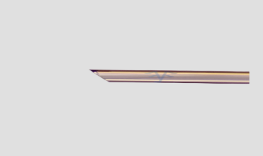
A reference photo or microscope image can preserve tip orientation for repeat builds
For a custom angled geometry, a simple approved image can make the drawing easier to interpret. It should supplement the controlled dimensions, not replace them. The next lot can then be compared for orientation before the part enters the optical fixture.
Shipping protection should keep the custom endface from touching the package or another fiber
The processed fiber end is the functional optical surface. If the project needs a protective tube, ferrule position, tip clearance or special tray, state that requirement in the purchase drawing. Do not let a custom polished tip move freely against packaging material during transport.
At receiving, leave the optical end protected until the inspection station is ready. A scratched or contaminated tip can create a coupling problem that looks like an incorrect angle or coating issue.
An angled lensed fiber should be replaced with the same geometry only when the system has not changed
If a laser diode, detector position, wavelength or mechanical path changes, the existing angle may no longer be the best choice. A replacement request should therefore verify the original source and target geometry rather than automatically copying an old part number into a redesigned instrument.
This is also why an angled lensed fiber should not be substituted with Feiyi’s tapered, two-faceted or four-faceted products without an optical review. Those geometries are designed to produce different spot shapes and coupling behavior.
Repeat orders should preserve the optical path that justified the angle in the first place
Once the first assembly is approved, retain the fiber type, source wavelength, selected 8°, 30°, 45° or 60° endface angle, orientation reference, coating requirement, connector or bare-fiber termination, finished fiber length, stripped length and the target beam direction. If the part is PM fiber, also preserve the polarization-axis convention.
Feiyi’s lensed fiber supplier article provides broader coupling context. For this angled product, the most useful purchasing record is the one that explains why the beam must leave the fiber in that particular direction. If a new engineer can reconstruct the source-to-target path from the drawing, the angle is no longer an unexplained catalog choice.
A prototype coupling result should be recorded with source position and tip orientation
When the first angled-fiber sample reaches acceptable coupling, save more than the measured power. Record the source wavelength, source-to-tip spacing, tip orientation, target location and any adjustment made to the holder. Without those conditions, a later sample can appear worse even when the fiber geometry is correct because the receiving fixture was rebuilt differently.
For an OEM handoff, this reference also helps separate supplier variation from assembly variation. If the new part matches the approved angle and coating but the source position has shifted, the correct action is to restore the fixture before changing the fiber specification. That protects a successful custom geometry from being redesigned around an unrelated mechanical drift.
[executed on device: SK-20260121JOTG (a251fff9-956e-47b5-9307-14fb53329ed2)]