Choosing a Lensed Fiber Supplier for a Spot Shape Your Assembly Can Actually Use
The smallest-looking fiber tip is not necessarily the one that delivers the useful light pattern. An engineer may need efficient laser coupling, a rectangular illumination region, a flat-top pattern or a turned optical path. A lensed fiber supplier needs to know which of those jobs the assembly must perform. Feiyi’s wedge lensed fiber and tapered lensed fiber provide different starting points; their published tip and far-field descriptions should be matched to the source and receiving optics. Define the required optical result, fiber type and alignment space before approving an end shape.
Ask a lensed fiber supplier for the useful optical result before a tip radius
A coupling application and an illumination application can value different outputs. The first may need close matching to a receiving optical mode; the second may need light distributed across a particular region. A radius, angle or attractive tip photograph cannot replace that functional requirement. Explain where the light comes from, where it must go and how the useful result will be evaluated.
A DFB laser coupling request should describe both beam axes
Feiyi lists DFB laser coupling among the applications for its wedge and tapered fibers. For a proposed coupling assembly, identify the source wavelength, spatial beam characteristics, polarization requirement and receiving fiber. If the beam differs along two orthogonal directions, give the supplier both descriptions. Do not reduce an asymmetric source to one approximate spot diameter.
Thorlabs’ laser-diode beam-shape technical note explains how unequal divergence and astigmatism can complicate a coupling task. These characteristics need to be determined for the actual source. A wedge geometry is a candidate to discuss, not evidence that any wedge automatically matches every diode.
For an OEM developing a compact laser assembly, provide the available alignment motions and mechanical clearance around the optical end. If the fixture cannot rotate the fiber or approach the source at the required location, an otherwise plausible shape may be unusable. The requested sample should correspond to the mounting and adjustment arrangement the prototype can actually support.
OZ Optics’ tapered-and-lensed-fiber document relates end shaping to mode matching and distinguishes coupling tasks from detector collection. That technical logic helps define the request. The optical target remains specific to the source, receiving interface and selected Feiyi construction; no coupling-efficiency number is implied by the product name.
The wedge lensed fiber’s radius and angle must fit the coupling geometry
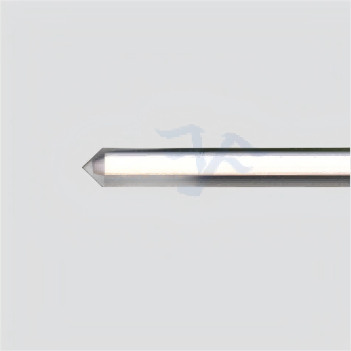
Feiyi’s wedge lensed fiber lists a tip radius of curvature from 8 to 12 µm, a wedge-angle range of 60–120° and applicable coupling far-field divergence of 15–40°. These are published customization ranges. Specify the desired geometry and optical conditions within an agreed build rather than ordering “the standard wedge” and assuming all values apply simultaneously.

Wedge orientation is separate from the PM fiber’s slow-axis reference
The wedge can have an important geometric orientation relative to the source beam. A PM fiber also has polarization axes that matter to the optical circuit. Define how those references relate in the completed item. A remote keyed connector does not fully describe the shaped end unless its relationship to the wedge orientation is part of the accepted drawing.
The wedge listing permits single-mode, multimode, PM and customized fiber materials, along with custom fiber and stripped-coating lengths. State the selected fiber construction, intended wavelength and the bare length the assembly needs. An optical-end fixture may need access to the shaped region while the remaining fiber requires mechanical protection. Those two needs should be reconciled before the sample arrives.
For a prototype using a PM wedge fiber, preserve the source orientation and the fiber’s accepted rotational reference during alignment. Compare results under controlled conditions instead of changing the tip position, source current and polarization reference together. A favorable transmitted-power reading is easier to interpret when the engineer knows which variable produced it.
The 15–40° divergence field is not a guaranteed coupling result for every source within that range. Obtain the supplier’s interpretation for the selected shape and clarify the reference direction and measurement convention. The approved specification should identify the required useful power or mode-coupling behavior without inventing an undocumented tolerance or test result.
Tapered, two-faceted and four-faceted fibers describe different light distributions
Feiyi describes the tapered fiber’s far-field spot as ring-shaped, the two-faceted fiber’s far-field pattern as flat-top and the four-faceted fiber’s pattern as rectangular. These distinctions are useful for choosing a family to investigate. They do not establish the dimensions, uniformity or efficiency of a completed assembly without an agreed optical specification.
The published ring-shaped far field belongs to a different output requirement from a compact focused spot. Its apex-angle range is 60–120°.
The listed flat-top far-field direction is relevant to an illumination-distribution discussion. Confirm the target plane and allowed variation.
The listed rectangular pattern and high-power diode-coupling application call for a defined source and receiving geometry.
A flat-top illumination requirement is not the same as single-mode coupling
Feiyi’s two-faceted lensed fiber lists endoscope illumination and DFB laser coupling among its applications. An illumination designer should define the required pattern at the relevant observation plane. A coupling engineer should define the source and receiving optical mode. The fact that one family lists both applications does not make their acceptance methods identical.
For an illumination prototype, specify whether the priority is the extent of the lit region, variation within that region or total collected light. A tip that gives a desired pattern in one plane may not give the same distribution at another distance. Preserve the test geometry when comparing samples. Published endoscope applicability is not a claim that the fiber is an approved complete medical device.
The four-faceted or pyramidal lensed fiber lists a rectangular spot and a 60–120° wedge-angle range. It is a separate candidate for a source or illumination requirement with a rectangular geometry. Confirm optical power, fiber type and acceptance conditions for the actual build; a high-power application label is not an unlisted wattage or damage-threshold approval.
An engineering team replacing a circular-output assumption with a rectangular requirement should update its drawings and measurements together. Record the orientation of the rectangle relative to the fixture, as well as the plane where it is evaluated. Otherwise, a rotated sample can appear to fail a receiving aperture even though the family selection was appropriate.
Angled lensed fibers can redirect a path without solving every reflection problem
Feiyi’s angled lensed fiber lists angle choices of 8°, 30°, 45° and 60°. Its applications include reducing back reflection, changing optical direction, sensor input and endoscope illumination. The chosen angle must correspond to the intended optical path and surrounding medium; it should not be selected solely because another assembly used the same nominal angle.
An 8° fiber-end choice does not define the complete reflected-light route
In a laser coupling assembly, an angled surface can affect where uncollected light reflects. The engineer still needs to examine the source, fiber-end geometry and other nearby reflecting surfaces. Thorlabs’ pigtailed-diode design discussion illustrates how an angled fiber input is used to redirect uncoupled reflection in a specific design. It does not establish a universal return-loss value for a Feiyi angled end.
For a turning-path request, define the required outgoing direction and the medium around the end. A nominal surface angle is not enough to establish the resulting path in every environment. Ask the supplier to confirm how the selected shape produces the requested direction, and agree an acceptance observation that the buyer can reproduce.
The angled fiber should also have a defined rotational reference in its mount. Turning the fiber around its own axis can turn the intended outgoing direction. If the instrument requires a replaceable optical end, preserve that reference in the fixture and product identification. A correct end angle attached to an undefined rotation remains an incomplete assembly specification.
Lensed fiber sample acceptance should match the eventual fixture
Feiyi’s lensed-fiber listings describe direct processing of bare fiber without auxiliary adhesives and coating applied to the fiber endface. Use those published construction descriptions when discussing the selected optical end. They do not identify the buyer’s bonding process, mounting adhesive, seal or a guaranteed survival condition for the completed assembly.
Ask what coating is included for the selected wavelength and which optical-end features are controlled in the drawing. Keep endface coating, geometric shape and required output behavior as separate approval fields. A requested coating does not establish a numerical transmission improvement unless that result is specified and supported for the delivered build.
SQS’s fiber-array document shows that lensed fibers can form part of larger optical-interface arrangements. For a Feiyi shaped end used in a buyer’s array or fixture, specify the actual position, orientation and remote termination. Do not assume that standalone tip availability establishes a supplied complete array with unlisted pitch accuracy or coupling performance.
For the DFB prototype, measure the useful coupled output at the agreed source condition and record the fiber position and rotation that produced it. Then check whether that condition can be retained by the intended fixture. The highest reading found during unrestricted bench motion may not be a usable production alignment if the housing cannot preserve it.
For an illumination prototype, evaluate the chosen ring, flat-top or rectangular pattern in the actual target plane. Keep the source and receiving aperture unchanged when comparing tip variants. This prevents an apparent product improvement that actually came from changing the observation distance or collection optics.
Specify the lensed fiber’s exposed length and protection around its selected tip
The listings allow custom fiber length and stripped-coating length, with optional FC, LC, SC and SMA connectors and PC/APC termination choices. Record the remote termination separately from the optical tip. A remote connector’s polish does not identify whether the optical end is wedge-shaped, tapered, faceted or angled.
Request protection that keeps the shaped end from touching a packing surface or being loaded by its own lead. Define how the exposed region will be supported during unpacking and installation. The delicate end needs a handling arrangement suited to its shape; ordinary connector caps at the remote end do not protect it. Agree the supplied protection without inventing a standard Feiyi shipping container.
The lensed-fiber listings give an operating-temperature range of −40 to +85°C. Confirm its application to the selected construction and the conditions of the buyer’s assembly process. An operating range alone does not qualify an unspecified bonding cure, cleaning chemical, sterilization method or complete medical instrument.
The existing Feiyi introduction to lensed-fiber coupling provides broader background. For an order, narrow the decision to one optical job: the useful coupled mode, required illumination pattern or defined outgoing direction. Approve the fiber, shaped end, rotational reference and fixture-based acceptance around that job. The tip drawing becomes meaningful when it describes light the assembly can actually use.