Working With a PM Fiber Coupler Manufacturer on an Unequal Optical Split
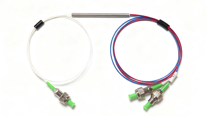
Sending half the available light to a monitor is often unnecessary when the main optical path needs most of the power. An unequal split can give the monitor a useful signal while preserving more power in the working branch, but the ratio must be defined with the operating wavelength and PM-axis conditions. A PM fiber coupler manufacturer should be assessed against those branch requirements. Feiyi’s 780/808/850 nm PM coupler and 980/1030/1064 nm PM coupler list unequal coupling-ratio options and 1×2 or 2×2 configurations for relevant wavelength families.
A PM fiber coupler manufacturer needs to know which branch is the monitor
Consider an optical instrument in which one branch carries the useful signal and another feeds a power monitor. The monitor’s sensitivity determines how much light it needs, while the main route has its own minimum delivered-power requirement. A 50/50 split is simple to describe but may spend more signal power than the monitor needs. Define the two destinations before selecting a ratio, rather than treating the outputs as interchangeable leads.
Feiyi’s coupler listings include ratio examples such as 10/90, 5/95 and 1/99. These are relevant candidates for an unequal monitoring arrangement, but the smallest tap is not automatically the best choice. A weak branch must still meet the monitor’s usable measurement range after its connectors and downstream path are included. Select the ratio against the expected optical input and the actual receiver requirement.
A 10/90 PM tap needs an unambiguous main-output designation
The order drawing should say which physical output receives the nominal 10% share and which receives the nominal 90% share. A ratio label by itself does not identify the lead that the assembly technician should connect to the main route. Record the port names, supplied lead identification and the destination of each branch. This matters particularly when a compact package hides the internal routing.
Thorlabs’ PM coupler and tap information provides general background on unequal branch ratios. That background helps frame the optical decision, but the supplier’s own wavelength, axis and connector conditions must govern the Feiyi assembly. Do not use a different manufacturer’s tap performance as the incoming limit for this order.
A 1/99 monitoring branch should be evaluated at the lowest useful source level
If the source output varies during normal use, the monitor must remain useful at the low end of that range. A 1% branch that works at the highest source setting may be inadequate during a lower-power measurement. Give the engineer’s minimum useful monitor signal to the supplier and include the monitor-branch interfaces in the budget. This avoids selecting a ratio solely to maximize the main-path number.
For a PM sensor with a small available return, that decision can be different from a high-power source monitor. The returning signal may leave little margin for either branch, and a balanced split may be appropriate when two measurements need comparable optical power. Keep the use case attached to the ratio. Feiyi’s listed options provide a selection space, not a reason to treat one ratio as universal across instruments.
PM coupler insertion loss includes the intended optical split
Branch insertion loss and excess loss describe different parts of the power accounting. Branch insertion loss includes the reduction caused by intentionally sending power elsewhere, while excess loss concerns additional loss beyond the nominal division. A monitor branch can therefore have a much larger insertion-loss figure than the main branch without indicating that the device is defective. The correct comparison is with the agreed ratio and measurement conditions.
| Nominal split | Ideal monitor share | Ideal monitor-branch loss | What the engineer still needs |
|---|---|---|---|
| 50/50 | 50% of the input | About 3.01 dB | Actual loss and uniformity of both branches |
| 10/90 | 10% of the input | 10 dB | Measured tap ratio and main-route allowance |
| 1/99 | 1% of the input | 20 dB | Monitor sensitivity at the lowest input level |
The illustrative values follow −10 log10 of the branch’s fractional power. They are calculations, not measured results for a Feiyi coupler. Add the actual excess loss, termination effects and remaining branch path when creating the instrument’s optical budget. If an offer gives only an insertion-loss figure without naming the output branch, clarify the measurement before comparing it with another offer.
Excess-loss acceptance should stay separate from tap-ratio acceptance
Feiyi’s 780/808/850 nm and 980/1030/1064 nm listings distinguish excess loss from the ratio information. Preserve that distinction in the order. Ask for the agreed ratio tolerance and the applicable excess-loss condition, then specify the permitted loss for each identified output. A single “low loss” requirement does not establish whether the weak branch has the intended share or whether the main branch has enough remaining power.
G&H’s PM coupler information also treats wavelength, ratio and polarization conditions as configuration choices. The general lesson is to compare complete conditions rather than isolated headline values. Any ratio tolerance, power limit or environmental qualification for the Feiyi build should come from the agreed Feiyi specification.
Choose the PM coupler’s port arrangement before dividing three measurements
Feiyi lists 1×2 and 2×2 arrangements in the two wavelength families above. Choose the configuration against the actual optical diagram: how many inputs exist, which branches are used, and whether an additional port has a defined function. An unused fiber lead should be identified and handled as the supplier specifies instead of being left as an unexplained part of the assembly. Port count is not merely a package description.
A separate three-branch requirement should trigger a different comparison. Feiyi’s PM 1310/1550 nm 1×3 coupler lists a 33:33:33 arrangement and wavelength ranges of 1310 ±20 nm and 1550 ±20 nm. It can be considered when three destinations need a distribution architecture in those bands. It should not be treated as an unequal 1×2 monitor tap simply because both products split light.
For a sensor team feeding three measurement channels, an improvised cascade of two 50/50 couplers does not produce three equal shares: one branch leaves at the first division while the other two share what continues into the second. That calculation alone is enough to reopen the proposed diagram before purchasing. The listed 1×3 product offers a different intended distribution, which should be compared against the three receivers’ requirements and verified on its own sample.
Its listed uniformity limit is 0.7 dB, and the product includes separate axis-type choices in the ordering information. Put those details beside the three receiver paths so that equal nominal shares are not mistaken for identical measured outputs under every condition. If the receivers need unequal shares instead, describe that requirement explicitly rather than ordering the 33:33:33 device and expecting the downstream connections to create the desired ratio.
A PM polarization beam splitter does not divide power in the same way as a fixed-ratio tap
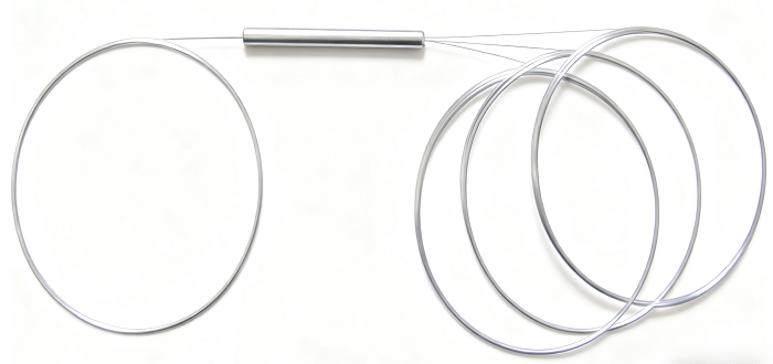
Feiyi also offers a 1550 nm 1×2 polarization beam combiner/splitter. That product separates or combines light according to polarization, whereas the coupler decision here concerns a defined power-sharing arrangement. If the instrument needs two polarization channels, review the polarization device. If it needs a small monitoring fraction from one optical signal, review the power tap.
Fujikura’s polarization beam-combiner information provides background on that separate device role. The procurement consequence is to write the required behavior into the drawing. Words such as “splitter” or “combiner” do not establish whether the component acts on power fraction, wavelength or polarization.
Similarly, Feiyi’s PLC Splitter – Mini belongs in a comparison where the project needs the appropriate passive distribution arrangement. It is not a substitute for an axis-sensitive PM tap on the strength of its output count. Keep the PM requirement and the intended branch behavior explicit when the purchaser compares different splitter families.
Accept PM coupling ratio at the chosen wavelength and launch axis
The two Feiyi PM coupler families identify different working wavelengths: 780/808/850 nm for one, and 980/1030/1064 nm for the other. Their fiber designations include PM780/PM850 and PM980/PM1060 respectively. A sample test at one wavelength should not silently approve a different wavelength variant. Identify which product and operating point the test result belongs to, especially when multiple instruments share the same connector format.
Feiyi lists a minimum extinction ratio of 20 dB in these coupler families. Confirm the applicable launch axis and measurement conditions for the purchased configuration. The PM requirement needs to apply to the used output branches, not merely to an unspecified point in the assembly. If one branch feeds an axis-sensitive component, record that interface in the optical drawing.
Ratio measurements should identify both outputs under one stable input condition
Reference the input power, measure the intended outputs and record which reading belongs to which lead. Keep the source and launch alignment stable between readings. A practical acceptance record should distinguish measured ratio, main-branch loss, monitor-branch loss and the polarization requirement. This avoids using a satisfactory total output as proof that the two branches have the correct individual shares.
OZ Optics’ PM fixed-coupler offering gives additional background on ratio and configuration choices. Use it to understand the questions a PM-coupler purchase raises, while keeping Feiyi’s order-specific acceptance values separate. Sample testing belongs to the selected wavelength, ratio, terminations and axis convention.
Feiyi’s coupler ordering information includes bare-fiber or jacketed lead choices and connector options. Decide whether the prototype and repeat-order measurement will include the delivered connectors. If the production instrument uses spliced leads while the bench sample is connectorized, document that difference before interpreting the branch losses. Otherwise the sample and production path may contain different interfaces even when the internal ratio is unchanged.
Lock the monitor lead and main lead into the PM coupler order description
For a 10/90 tap, the accepted drawing should identify the 10% monitor output and 90% main output, together with the wavelength, PM fiber, port arrangement, axis, connector choice and lead lengths. Feiyi’s listings show several package and pigtail constructions, so confirm the selected mechanical version rather than treating the ratio as a complete part description. The monitor lead must reach its detector without changing the agreed connection path.
Request individually identifiable branch leads and protection appropriate to bare or connectorized fibers when the approved samples are packed. In a mixed order containing 10/90 and 1/99 taps, each assembly should remain distinguishable without energizing it. Agree that identification and the lead restraint with the supplier, rather than assuming that output color always defines the tap percentage. The published product choices do not promise a standard labeling convention or a particular dispatch date.
Feiyi’s PM fiber coupler explanation provides wider context for the available applications. For the current instrument, keep the decision narrower: the monitor must have enough light at the lowest intended input while the main branch retains its required margin. Approve the ratio only when both branches meet those conditions in the same tested configuration.
Give purchasing the accepted branch names, not just “PM coupler, low loss.” A manufacturer that can resolve the two output requirements against an agreed wavelength and axis specification gives the engineering team a reproducible component choice. That is the useful endpoint for this order: a monitor that can measure and a main route that can still do its job.