980 1550 WDM Coupler Supplier: Identify the Pump, Signal and Common Fibers
A pump-combining component needs more than two wavelength numbers on an order. Engineers evaluating a 980 1550 WDM coupler supplier should identify the pump, signal and common fibers, their permitted optical bands and the power conditions before selecting a package. Feiyi’s three-port 980/1550 and 1480/1550 FWDM range provides the relevant starting point. The FWDM 59 specification separates a 965–1000 nm reflection band from a 1525–1600 nm pass band; first confirm that these port roles match the intended amplifier or instrument.
The procurement question is not whether a device is generically called a coupler. It is whether its wavelength routing, fibers and optical limits fit the actual assembly. A wavelength-selective component, a power-ratio coupler and a complete EDFA perform different jobs. Keeping those jobs distinct prevents an apparently similar three-fiber item from becoming the wrong component in the pump path.
Map the FWDM 59 pump and signal paths before selecting connectors
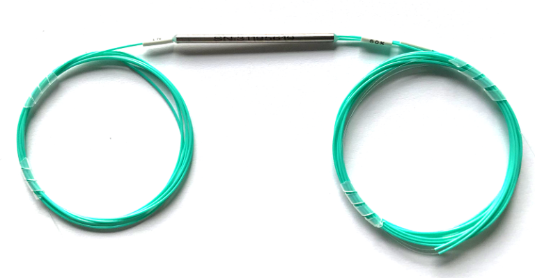
Feiyi’s FWDM 59 row lists 965–1000 nm for the reflection band and 1525–1600 nm for the pass band. In a proposed 980 nm pump and 1550 nm signal arrangement, those bands identify the initial wavelength routing to examine. Confirm the common port and permitted direction with the approved device diagram. The port names must follow the configured component rather than the physical order of its leads in a photograph.
HI1060 common and reflection fibers are part of the 980 nm configuration
The FWDM 59 fiber entry assigns Corning HI1060 fiber to the common and reflection ports and SMF-28e to the pass port. That distinction matters when the component is spliced into an amplifier assembly. The design should identify which lead reaches the pump and which reaches the signal path, together with the intended splice interfaces.
An amplifier OEM can have a correct optical band selection and still need to resolve its fiber connection method. Do not reduce the fiber requirement to “single mode, three ports.” Preserve the named fiber assignment in the approved drawing and order. If a different fiber is proposed, compare it with the assembly’s optical and splice requirements before accepting the change.
The 500 mW handling entry is not an EDFA output rating
The FWDM page lists maximum power handling of 500 mW. Obtain confirmation of the applicable port conditions and any additional limits needed for the actual pump and signal arrangement. The entry does not define an arbitrary pulsed-power, peak-power or high-power amplifier qualification.
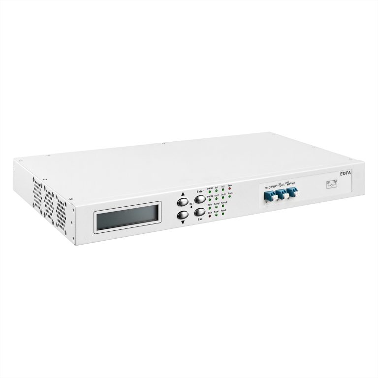
Feiyi’s EDFA equipment information describes a complete amplifier with its own interfaces and controls. Its equipment-level output entries should not be transferred to the passive FWDM component. Likewise, the passive filter’s power limit does not establish the gain or output behavior of a completed amplifier.
Use the 980 1550 WDM coupler supplier’s port-specific limits
The FWDM 59 table gives pass-channel insertion loss no greater than 0.9 dB and reflection-channel loss no greater than 0.7 dB. It lists pass-channel isolation at least 30 dB and reflection-channel isolation at least 15 dB. Keep each number associated with the port and wavelength condition it describes. One combined loss or isolation figure would hide the difference between the two optical routes.
| FWDM 59 route | Listed band | Loss limit | Isolation entry |
|---|---|---|---|
| Pass | 1525–1600 nm | ≤0.9 dB | ≥30 dB |
| Reflection | 965–1000 nm | ≤0.7 dB | ≥15 dB |
For acceptance, agree the optical direction and the unwanted wavelength used when checking isolation. A result without those conditions cannot establish which port relationship was evaluated. Do not interpret the higher pass-channel figure as the guaranteed isolation of every path in the three-port assembly.
Connectorless loss must remain separate from the delivered interfaces
Feiyi states that the specifications exclude connectors and indicates an additional 0.2 dB loss per connector. Include the selected termination arrangement in the assembly budget. A connectorized delivery and a bare-fiber splice installation are different reference conditions even when the passive component is the same.
A buyer comparing a sample against a completed amplifier should identify the reference planes of both measurements. The amplifier result includes more components than the FWDM itself. Preserve the passive device measurement separately so that a change in a connector, splice or downstream component is not automatically assigned to the filter.
The product lists PDL no greater than 0.1 dB, directivity at least 50 dB and return loss at least 50 dB. Those entries do not establish a polarization-maintaining axis or extinction-ratio specification. If the assembly requires polarization-maintaining operation, confirm the required device and fiber behavior explicitly rather than treating low PDL as PM qualification.
Distinguish 980/1550 filtering from 1480/1550 filtering
The neighboring FWDM 54 column lists a 1530–1565 nm pass band and a 1450–1490 nm reflection band. Its pass and reflection insertion-loss limits are 0.6 dB and 0.5 dB respectively. This provides a different wavelength-routing option. It does not supply the pump-band approval for an assembly intended to use the FWDM 59’s 965–1000 nm reflection path.
An engineering team comparing pump arrangements should keep the selected column in each proposed bill of materials. If the pump wavelength changes from the 980 nm region to the 1480 nm region, review the filter band, fiber assignment and assembly interface together. Merely changing one wavelength in the purchase description can leave the old configuration’s fibers or limits attached to the new order.
The page presents both arrangements in one product range, which is useful for comparison but can create ambiguity in an abbreviated stock record. Identify FWDM 54 or FWDM 59, the configured bands and the port map on the approved document. A common product title should not erase the distinction between the two columns.
As historical technical background, Thorlabs’ archived 980/1550 WDM documentation describes combining different wavelength bands in one fiber path. It helps explain the component’s function; its ratings, fiber choices and old product listings are not Feiyi specifications or current supply evidence.
Separate wavelength combining from power-ratio splitting
Feiyi’s single-mode dual-window coupler is relevant when the assembly needs a power-coupling ratio within its specified wavelength windows. That is a different purpose from assigning pump and signal wavelengths to separate filter paths. A two-window name should not be interpreted as automatic equivalence to a 980/1550 WDM.
The general three-port FWDM device includes other transmission/reflection combinations used in optical networks and instruments. Its selection should follow the stated bands of the configured version. A common three-port structure does not approve it for the FWDM 59 pump-fiber arrangement.
Consider an instrument buyer who needs a monitor tap rather than a pump combiner. A power-ratio coupler may be the relevant family to examine, subject to its wavelength and loss limits. If the objective is to route two distinct wavelength bands, the filter specification becomes central. Define the optical job before comparing package size or the number of fiber leads.
Choose the FWDM package around the actual amplifier assembly
The range lists a Φ5.5 × 38 mm package for 250 µm and 900 µm fiber arrangements and a 90 × 20 × 10 mm package for 2.0 mm and 3.0 mm options. Review the selected package with the intended lead routing and retention. Body dimensions alone do not identify the bend allowance or splice access needed by the complete assembly.
A compact amplifier board may prefer a smaller component outline while still requiring protected routing to the splice tray. A serviceable instrument may prioritize accessible connectorized leads. Those are different integration conditions; select the protection and termination with the package instead of assuming every variant uses the same lead arrangement.
The ordering information includes several fiber lengths and connector choices. State the actual length, jacket or tube, polish and connector for each configured port. For mixed-fiber FWDM 59 leads, retain the named fiber assignment as well. This lets the receiving team identify the intended connection without treating every lead as physically or optically identical.
The listed operating range is −10 to +70°C. Evaluate it at the component location in the equipment. A complete EDFA chassis can create local thermal conditions different from room ambient. The table does not establish qualification for every thermal cycle or environmental exposure specified by the equipment buyer.
For a bare-fiber amplifier build, show the HI1060 common and reflection leads and the SMF-28e pass lead on the assembly drawing before choosing splice positions. The surrounding fiber arrangement may be different on each side of the device. Obtain the required connection and test conditions for those interfaces rather than assuming that the three leads can be exchanged without changing the assembly.
For a connectorized instrument, distinguish the FWDM 59’s component limits from the added interfaces. A buyer comparing the pass and reflection measurements should retain the actual termination used on each route. Replacing one bare-fiber connection with a connectorized lead changes the reference arrangement; the catalog’s connectorless loss entry should not be presented as the complete delivered path loss.
If the order mixes FWDM 54 and FWDM 59 units, make their different reflection bands visible in the receiving labels. The 1450–1490 nm and 965–1000 nm arrangements have different intended pump-path discussions. A shared tube or box outline cannot identify which column applies. Receiving staff should reconcile the configured bands and fiber assignment before the device reaches the assembly bench.
When the equipment design requires limits beyond the table’s −10 to +70°C operating range or its 500 mW handling entry, retain those requirements as open configuration questions. The range’s customization statement is a reason to request an approved specification, not evidence that the proposed extended condition has already been qualified.
Make the pump-combiner acceptance record usable for the next build
Agree acceptance evidence that identifies the configured bands, port directions, fiber types and connector inclusion. Keep the selected FWDM column visible in the test record. If the amplifier team later changes the pump source or lead termination, review the effect on the filter approval rather than treating the old result as unrestricted permission.
For shipment, request protection and labels for the different fiber leads and the selected package. Agree the actual packing and dispatch arrangement with the order; the product page does not establish a standard export kit, available inventory or a guaranteed lead time. The useful requirement is that the delivered device can be identified against its approved pump/signal/common drawing.
Feiyi’s FWDM explanation gives broader wavelength-routing context. For this component, retain the narrower decision: whether the FWDM 59 bands, mixed-fiber assignments and port-specific limits fit the intended 980/1550 assembly.
Release the order with the pump, signal and common leads identified before anyone splices them into the equipment. If the design requires a different band, PM behavior or power condition that is not established here, obtain the corresponding configured specification first. Three fiber leads and two familiar wavelength numbers are a starting description; the approved port-and-fiber map is what makes the component usable.