Multimode Fiber Optic Coupler Supplier: Make the Launch Condition Part of Acceptance
Two laboratories report different split ratios for the same multimode assembly. Before requesting a different device from a multimode fiber optic coupler supplier, compare how each laboratory launches and collects the light.
Feiyi’s multimode fiber coupler is relevant to equipment builders, distributors and optical-network buyers needing a defined multimode power division. Its specification table identifies 50/125 and 62.5/125 fiber, 1×2 or 2×2 ports, and 850, 1310 or 1550 nm center options. Begin with the actual input fiber, required branch powers and test arrangement. The translated product name should not be used to infer a manufacturing process that the specification does not establish.
A multimode fiber optic coupler ratio is measured under a launch condition
A coupling ratio describes how the input light is divided between the relevant outputs. For this product, the receiving team needs more than a percentage on an order line. It needs to know which input is illuminated, what enters the multimode fiber and how the output powers are collected. Otherwise, a ratio discrepancy can originate in the measurement arrangement.
Keep 50/125 and 62.5/125 coupler acceptance separate
Both fiber sizes appear in Feiyi’s multimode listing. Identify the selected size at every relevant interface, including the launch and receiving leads. An adapter does not make an undocumented mixture of core sizes equivalent to a consistent fiber path. If a mixed-fiber connection belongs to the actual equipment, include it deliberately and evaluate its effect in the system qualification.
A distributor serving laboratories with different multimode sources should retain separate configuration records for these fiber choices. The coupler housing can look the same, so the fiber designation needs to remain on the purchase record and receiving label. A stock description that says only “multimode, 50/50” loses an important optical distinction.
State the launch used for the 850 nm split measurement
The source and its coupling into the input fiber can influence the modal distribution. Preserve that arrangement when comparing devices or investigating different receiving results. A source setting alone is insufficient if the lead, input coupling or intermediate connection changes between measurements.
Thorlabs’ multimode fiber study illustrates that input conditions affect the emitted distribution. For a coupler purchase, this is a reason to record the launch and collection arrangement. It is not a reason to copy the study’s experimental fiber, source or measured behavior into a Feiyi specification.
When the equipment uses a particular installed source, qualify a sample with that source or a justified equivalent. A receiving bench can still use a repeatable reference arrangement for incoming inspection, but explain how its result relates to the equipment’s requirement. That separation prevents an incoming test from being mistaken for a complete system approval.
Read coupling ratio, excess loss and branch loss as different quantities
Feiyi’s multimode table presents a 50/50 case and separates excess loss, maximum insertion loss and uniformity. These entries are not competing descriptions of one measurement. A buyer evaluating the device should understand what each quantity includes before comparing a supplier result with the expected branch power.
Use comparable output collection when measuring the branches. If one output reaches a large-area detector directly while the other passes through a different receiving fiber, the readings include different paths. Such an arrangement can be useful for qualifying the finished instrument, but it should not be described as a clean measurement of the coupler’s division alone. Identify which result belongs to the component and which belongs to the equipment.
The table also gives an 800–1600 nm wavelength range alongside center-wavelength choices. Confirm the actual selected configuration and its accepted behavior over the required band. A broad family-level range does not establish an unchanged coupling ratio and loss at every wavelength for every ordered version. If a monitoring channel must operate at more than one wavelength, include each required wavelength in the approved sample record.
When measuring sequentially with one power meter, preserve the input setting while moving between output branches. If the source drifts during the sequence, a calculated ratio can change without any coupler change. A recorded input reference and a repeat observation after the branch measurements can help identify that uncertainty. They do not justify creating a tighter repeatability guarantee than the delivered specification provides.
| Quantity in the coupler decision | Question the buyer is answering | Information to retain |
|---|---|---|
| Coupling ratio | How is power divided between outputs? | Input port, wavelength and launch |
| Branch insertion loss | How much input power reaches this output? | Specified branch and reference planes |
| Excess loss | How much power is not recovered across the relevant outputs? | Output collection method and normalization |
| Uniformity | How closely do the intended output powers agree? | Selected split and comparable readings |
A 50/50 division does not make branch loss zero
A power-dividing device intentionally directs only part of the input power into each branch. The insertion loss of one branch therefore includes the intended division as well as other losses within the measured path. Rejecting the coupler because a branch does not transmit all input power misunderstands the device’s function.
Feiyi lists typical excess-loss values of 0.7 and 1.1 dB for the corresponding multimode grades in the 50/50 table. Use the approved grade and measurement conditions when discussing acceptance. Do not substitute a single-mode product’s lower excess-loss entry for the multimode requirement or combine unrelated grade columns into a new limit.
The conversion chart also lists unequal ratios. Some catalog ratio/loss entries need clarification before they become contractual numerical limits. A buyer requiring a 10/90 or another asymmetric division should obtain the approved output definitions and loss limits for that exact configuration. The selected ratio alone does not provide a trustworthy substitute for those definitions.
If the low-power branch feeds a monitor, specify its usable power range as part of the instrument requirement. A ratio that is appropriate for the main transmission path may leave the monitor outside its useful measurement range. Conversely, changing the ratio to satisfy the monitor can reduce the power available to the main optical channel.
Use the multimode coupler supplier’s port drawing for a 1×2 or 2×2 order
The product table identifies 1×2 and 2×2 configurations. Specify which physical leads are inputs and outputs in the intended arrangement. A 2×2 assembly can introduce another input-related question that a 1×2 receiving procedure does not address. Obtain the relevant port drawing rather than identifying the function by the number of loose fibers.
An instrument engineer using a coupler to monitor a source may need one main output and one observation branch. A different equipment builder may use a 2×2 configuration within a bidirectional measurement path. Those are hypothetical design situations, not reported customer installations, and they should receive distinct sample conditions.
For a spare purchase, recover the original port labels before disconnecting the old assembly. If the equipment wiring does not preserve those labels, record its connections and agree the replacement mapping. A physically similar coupler inserted with the wrong branch assignment can alter monitor readings even when the device meets its own specification.
Single-mode couplers and PLC splitters belong to different approval paths
Feiyi’s single-mode coupler is an alternative when the entire source and transmission arrangement is single-mode. Its fiber and optical table should then become the basis of the purchase. It is not a higher-performing replacement for an installed multimode device simply because a loss value is smaller.

The single-mode dual-window coupler addresses 1310/1550 nm operation with the published dual-window conditions. It is useful when a single-mode path must support those windows. That wavelength overlap does not make it a suitable replacement for a 50/125 or 62.5/125 input.
The mini PLC splitter addresses a different splitter configuration and port-count discussion. Review it when the design needs the relevant published splitter arrangement. Do not transfer the multimode coupler’s launch, ratio or packaging approval directly to the PLC product; the optical construction and specified application need their own review.
Feiyi’s existing guide to ratio and wavelength windows provides a wider explanation of splitter purchasing. Here the narrower decision is how to approve a multimode device under a defined launch. Keeping that decision separate helps prevent a broad splitter comparison from replacing the specific test agreement.
Choose the multimode coupler package around its actual leads
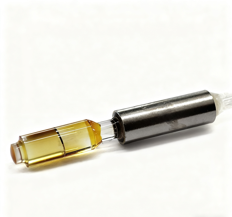
The listing gives stainless-steel tube packages D, E and F at 3 × 45, 3 × 54 and 3 × 60 mm, and a case package G at 10 × 20 × 90 mm. The associated pigtail styles include bare fiber, 900 µm loose tube and cable options according to package. The package selection should reflect how the assembly will be retained and terminated.
Package D and E need a defined bare-fiber handling route
Feiyi identifies 250 µm bare fiber for those package styles. A compact tube may fit the optical module well, but the receiving and assembly process must protect the exposed leads. Establish how much free fiber is needed for joining and how the joint will be supported in the completed module.
When the buyer’s process adds connectors, separate the supplied coupler acceptance from the later connectorized assembly result. If the supplier delivers the final termination, include the connector and fiber length in the approved configuration. Mixing these two boundaries can lead to a dispute over losses introduced outside the delivered component.
Package G changes the mechanical integration, not just the carton size
The larger case and cable options can be appropriate when the coupler belongs in a field-accessible or instrument-wiring arrangement rather than a densely integrated optical module. Confirm the mounting space, lead exit direction and connector access. The housing choice should not be made solely to simplify receiving inspection if it creates a poor installation route.
The product lists a 1 m pigtail or custom length. Define which leads require which usable length, especially for a 2×2 arrangement where all exits may not follow the same equipment route. For transport, agree support for the tube or case and its leads separately; no catalog information establishes a universal packing method or dispatch commitment.
Resolve a multimode ratio discrepancy before changing the purchase
If two measurements disagree, first compare the selected wavelength, input port, fiber sizes and reference planes. Then compare the launch and output collection. Check connections under a clean, repeatable arrangement before treating the result as evidence that the supplied grade is wrong. This diagnosis preserves the distinctions that matter to a multimode split.
A distributor should require the configuration identifier and corresponding result to travel together. An OEM should retain the approved bench arrangement alongside the equipment qualification. Neither needs an invented factory-capacity claim to establish a useful procurement file; it needs evidence for the exact coupler and the intended optical conditions.
Place the order when the branch assignment, input launch and grade-specific limits can be read together without assumptions. If the asymmetric loss chart remains unclear, resolve that configuration first. Changing suppliers while carrying the same undefined multimode test arrangement can simply reproduce the original disagreement.