Armored Fiber Optic Connector Supplier: Match Mechanical Protection to the Termination
Steel protection can keep a fiber termination from being damaged mechanically, but it cannot make an incompatible ferrule mate correctly or turn a dirty end face into a low-loss connection. A buyer selecting an armored fiber optic connector supplier for an industrial instrument should establish the mating interface and optical acceptance first. Feiyi’s armored connector listing addresses harsh industrial environments and offers several connector families. Use it to discuss the protected termination, then separate the protection requirement from any environmental qualification the finished equipment needs.
This purchase is relevant to OEMs, maintenance teams and integrators whose fiber connections face handling or mechanical exposure. It is less straightforward when the real requirement is a sealed enclosure, an outdoor assembly or a qualified military interface. The word armored alone does not supply the ingress rating, sealing arrangement or test evidence for those applications.
What should an armored fiber optic connector supplier actually deliver?
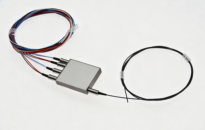
First define the boundary of supply. The Feiyi product is called an armored connector and its photograph shows protected fiber terminations. State whether the purchase includes the connector, protected lead, final cable length and opposing termination. A supplier cannot establish a repeatable assembly from an item description that leaves the delivered object unclear.
A maintenance team replacing a lead inside a moving equipment cabinet may need the protection to cover the section exposed to handling, while the connector still mates to a fixed optical port. An instrument builder may instead need a short protected termination between a sensor and an internal patch point. Those situations can require different lead lengths and exit arrangements even if both use an LC interface.
FC, SC and LC names do not settle PC, UPC and APC mating
Feiyi lists FC, SC and LC among its interface options. Confirm the connector family, end-face geometry and mating arrangement together. A connector that physically approaches the port can still be the wrong optical termination. An angled-contact requirement should not be reduced to the connector’s outer housing name on a purchase line.
The table presents insertion-loss values of no more than 0.3 dB and separates return-loss figures according to the listed connector and fiber conditions. The single-mode FC/SC/LC columns include PC, UPC and APC entries. Use the column corresponding to the selected assembly; do not assign an APC return-loss figure to a physical-contact termination because it is the best number in the row.
For example, the corresponding single-mode columns list return loss of at least 45 dB for PC, 50 dB for UPC and 60 dB for APC, while the multimode PC entry is 35 dB. These distinctions help a buyer specify the optical configuration without upgrading the description by accident. Preserve the selected column with the order, and confirm that the mating port and receiving test use that same configuration.
If the equipment has both single-mode and multimode channels, create separate descriptions. The optical requirement changes with the fiber and selected polish, while the armored exterior may look similar. Receiving staff should identify the assembly from its label and approved configuration, rather than guessing the fiber type from the protective hardware.
Mechanical armor is different from an ingress-protection rating
The product description emphasizes industrial and military environments, mechanical endurance and repeatability. Treat those as the published positioning of the product. It does not establish a particular ingress-protection classification, qualification standard or approval for every military platform. A buyer with such a requirement should obtain the applicable approved drawing and evidence before assigning that qualification to the order.
The protection also needs a physical endpoint. Show where the armored section begins and ends, what it can contact inside the equipment and where the cable is restrained. If the armor ends beside a sharp panel edge, the unprotected transition can become the weak location. That problem is solved by the route and retention arrangement, not by an optimistic description of the connector body.
For industrial terminations, approve three separate interfaces: the optical mating face, the protected cable transition and the equipment’s restraint point.
Inspect the armored termination without confusing strength and transmission
Feiyi’s table includes mechanical and optical entries, but they answer different questions. A compressive-strength entry does not verify insertion loss after the buyer’s intended handling event, and a good optical measurement does not establish the cable’s behavior under an undefined force. Keep the test condition beside each acceptance requirement.
The catalog’s force entry needs a fixture and loading direction
The listed compressive-strength expression is F > 300 N. Before using that value as a purchase criterion, ask how force is applied, which part is supported and what constitutes failure. A value without a fixture description cannot be transferred confidently to a pull, bend, crush or enclosure-retention test.
For an OEM exposing the protected lead to repeated service handling, define the actual contact points. If technicians pull on the lead to disconnect a port, identify whether that action is allowed and how the connector should be released. Mechanical protection can create confidence that leads to rough handling; the assembly instructions should remove that ambiguity.
Optical repeatability requires clean mating faces
Cleanliness remains necessary even when the cable is protected. The Fluke Networks inspection guidance recommends inspecting fiber end faces before connection and confirming the result after cleaning. The practical implication is that armor and protective caps do not remove the need to inspect the actual optical interface.
Agree the mating adapter and reference lead used to check insertion loss. If a protected lead arrives with a connector that is tested through an unsuitable adapter, the receiving result can be attributed to the wrong part. Record the fiber type and polish of both sides of the connection when diagnosing a failed optical reading.
The listing includes a service-life entry above 1,000 operations. Ask for the applicable operation definition if the equipment must meet a specific mating-cycle requirement. Do not interpret the number as a warranty period or proof that the finished installation has passed the buyer’s complete maintenance sequence.
Use ordinary patch cords when protection is not the actual constraint
Feiyi’s optical patch cord range is relevant when the principal requirement is a defined fiber link and termination within a protected cabinet. An ordinary cord may be the appropriate configuration if the equipment already shields the cable from mechanical exposure. Adding armor can change routing space and the transition at the connector, so protection should have a stated purpose.

For a distributor stocking replacements, it can be useful to keep ordinary patch cords and protected industrial terminations in distinct item groups. A technician requesting the same connector type may still need a different cable construction. Stock records should preserve that distinction instead of offering an apparently similar connector as the same assembly.
The MPO/MTP patch cord serves a different interface, connecting multiple fibers within one termination. It can be relevant in a dense optical system, but it is not an armored single-fiber substitute. Fiber count, connector orientation and mating details add decisions that the industrial FC/SC/LC lead does not resolve.
Feiyi’s 1U modular patch panel addresses organized rack termination and cable management. A panel can support the equipment’s routing plan, while the armored lead addresses exposure along a particular cable section. The panel listing’s compatibility wording should be verified against the intended configuration; it does not certify an unrelated armored connector for a proprietary system.
These products belong in one equipment review when they form a real optical route. They should not be bought as a bundle merely because all involve fiber connectors. Identify which product terminates the instrument, which carries the link and which organizes the rack. Then establish the mating interface between each pair.
Review the armored lead at its cable exit and enclosure boundary
The cable exit is where a protected termination meets the rest of the installation. Measure the available space and the direction in which the lead must leave the port. An assembly that mates correctly but immediately bends against the enclosure can create strain that was absent from the supplier’s loose-part optical test.
An industrial sensor cabinet may contain ordinary patch leads behind a panel and an armored section outside it. Specify how that section passes through the cabinet and where its load is retained. If sealing is required at the boundary, identify the sealing component separately. The protective cable construction does not automatically create a sealed panel penetration.
The −40 to +80°C listing does not qualify the complete cabinet
Feiyi gives −40 to +80°C as the connector’s operating-temperature range. Compare the actual connector location with that range, including local equipment heating. If a project also imposes humidity, chemical exposure or repeated temperature transitions, those requirements need evidence for the selected assembly and installation; the temperature row alone cannot answer them.
Where a protected termination is being sampled, first establish the optical reading in a defined, clean connection. Then evaluate the planned cable route and mechanical retention. If the buyer has an environmental approval procedure, apply it to the configuration that will be delivered. Record any additional protection fitted by the buyer so it is not mistaken for a feature of the supplied connector.
Receiving an armored connector order should preserve the approved construction
For this product, packing requirements should protect the end face and prevent the armored lead from transmitting a load to the connector during transport. Identify the cap or protective arrangement needed at each termination, and agree how the assembly will be restrained without damaging its transition. The request should refer to the actual lead construction and length.
Ask for item identification that distinguishes the connector family, polish, fiber and protected assembly. If several versions share a carton, each should remain identifiable after unpacking. A receiving operator should not need to connect a part to a live instrument simply to determine which purchase line it belongs to.
The shipping record should state the delivered assembly and any accessories included in its approved configuration. Dispatch date, packaging method and lot documents require agreement with the order; there is no published basis here for a universal stock or lead-time promise. For a service team, prioritize the exact replacement construction over an assumed faster substitute with the same outer connector.
Feiyi’s discussion of polarization-critical patch-cord interfaces is relevant if the installed lead must also preserve an axis. Armor does not establish that optical function. Keep the protection requirement and any PM requirement separately defined, with evidence for both before approving the assembly.
Release the industrial termination order when its optical mate, protected transition and enclosure restraint are all described. If the unresolved requirement is sealing, a particular mechanical qualification or polarization behavior, resolve that requirement in the configuration record first. Buying a stronger-looking lead cannot compensate for a missing interface definition.