CWDM MUX DEMUX Supplier: Plan Channels, Loss and Packaging for the Installed Network
A buyer comparing a CWDM MUX DEMUX supplier should start with the fibers and wavelengths already installed, not with the largest channel-count option in the catalog. CWDM is often selected when several services must share one fiber without the tighter spacing and wavelength-control requirements of a dense-channel system. The practical questions are therefore simple but specific: which coarse wavelengths are active, which ones are reserved for expansion, how much loss can the link absorb, and whether the assembly belongs inside equipment or in a serviceable rack.
Feiyi publishes 4CH, 8CH and 16CH CWDM Mux/Demux products, a CWDM Mux Demux in 1U Rackmount, a CWDM OADM Module and a 3 Port CWDM Device. These are not just different sizes. They address end-point multiplexing, intermediate add/drop and two-band routing in different ways. An operator or distributor should choose by topology first and package second.
A CWDM MUX DEMUX supplier should confirm the 20 nm wavelength plan before quoting ports
ITU-T G.694.2 defines a CWDM wavelength grid with 20 nm channel spacing. Feiyi’s published CWDM Mux/Demux specification lists channel wavelengths from 1270 to 1610 nm or 1271 to 1611 nm, depending on the selected grid convention, with 20 nm spacing and a channel passband of at least 13 nm at the published -0.5 dB condition.
A four-channel build is not merely an eight-channel unit with unused adapters
Feiyi publishes separate 4CH, 8CH and 16CH products. The insertion-loss limits rise with channel count in the shared specification: up to 1.5 dB for 4 channels, up to 2.5 dB for 8 channels, and for 16 channels a low-loss option up to 3.5 dB or a standard option up to 4.5 dB. That change belongs in the link budget before a buyer decides to “leave room for future channels.”
Consider a carrier extending an existing fiber route that currently needs four wavelengths. Ordering sixteen channels may look convenient for expansion, but the higher module loss, larger interface count and cabinet space still need to fit the present system. A planned expansion is a valid reason for more channels; avoiding a future purchase is not enough by itself if today’s optical margin is already narrow.
The receiver should be checked against adjacent-channel isolation, not only insertion loss
Feiyi’s CWDM specification lists adjacent-channel isolation of at least 30 dB and non-adjacent isolation of at least 40 dB. These values describe different leakage paths. A receiving port next to a stronger neighboring channel can face a different interference condition from one separated by several coarse channels.
For commissioning, label the channels by wavelength and measure the path that matters to the receiver. If a test report records only a common-port loss number, it does not show whether the unwanted neighboring wavelength is sufficiently rejected. The supplier and buyer should agree which channels require acceptance measurements before production release.
Choose the CWDM product around the network node, not around a generic module name
The same wavelength plan can appear at an end terminal, a mid-span node or a simple two-band interface. Each location calls for a different physical and optical arrangement. Feiyi’s range provides several starting points, but the project schematic must decide which family belongs at each node.
End-point multiplexing favors a defined Mux and Demux pair
At the ends of a point-to-point fiber, one assembly combines the individual wavelengths and the other separates them again. Feiyi’s ordering information distinguishes Mux, Demux and Mux+Demux configurations. That distinction should stay visible in purchase records and site labels.
A contractor installing both ends should not rely on identical housings to indicate direction. Mark the common fiber and every channel port in the installation drawing. If the two ends use different connector arrangements because of legacy patch panels, record that difference before the supplier builds the assemblies.
A CWDM OADM belongs at a site where selected wavelengths leave the trunk
A CWDM OADM Module is useful when one or more wavelengths are added or dropped at an intermediate site while other wavelengths continue through the line. The order should name the wavelengths that are dropped, the wavelengths that are added, and the channels that remain on the express path.
A municipal or campus network may begin with two sites and later add a remote building. In that case, an OADM can make more sense than breaking every wavelength out at the intermediate node. The buyer should design the wavelength route first rather than purchase a standard Mux/Demux and discover during installation that an express path is missing.
A 3 Port CWDM Device suits a narrower wavelength-routing problem
Not every CWDM requirement needs four or more channels. Feiyi also lists a 3 Port CWDM Device for applications that need a common port and wavelength-specific routing with a much smaller channel count. This can be a better component-level fit for equipment builders that are combining or separating two spectral regions inside an instrument.
An OEM should not use the appearance of the housing to decide between a 3-port device and a multi-channel module. The functional block diagram should state what enters each port and what must leave each port. Once that is clear, the supplier can map the request to the proper family.
A CWDM MUX DEMUX supplier must keep optical performance tied to the selected channel count
It is tempting to copy one acceptance limit across 4-, 8- and 16-channel products. Feiyi’s published data shows why that can be wrong. Insertion loss changes with channel count, while common parameters such as isolation, directivity and return loss remain separate requirements.
Use the published passband and temperature limits as component boundaries
The CWDM specification lists a passband of at least 13 nm and wavelength temperature shifting no greater than 0.002 nm per degree Celsius. Insertion-loss temperature sensitivity is listed at no more than 0.5 dB. The operating-temperature range is -10 to +70 degrees Celsius and storage is -40 to +85 degrees Celsius.
These are component-level values. An outdoor cabinet or industrial enclosure may experience additional connector contamination, patch-cord bending and thermal behavior that the Mux/Demux cannot control. The system owner should build margin around the complete path rather than treat a component temperature table as a guarantee for the whole enclosure.
PDL, PMD and power limits still matter in a coarse-channel system
Feiyi’s CWDM page lists polarization-dependent loss no greater than 0.2 dB, polarization-mode dispersion no greater than 0.1 ps and maximum power handling of 300 mW. These values may be less visible to a buyer focused on wavelength count, but they still belong to the approved specification when the link or optical source is sensitive to them.
A CATV or amplifier-related route, for example, may place a different power condition on the common port than a low-power monitoring link. The buyer should state the expected optical power at the device instead of assuming every passive WDM path is power-agnostic.
Packaging changes how a CWDM MUX DEMUX supplier should label and protect the assembly
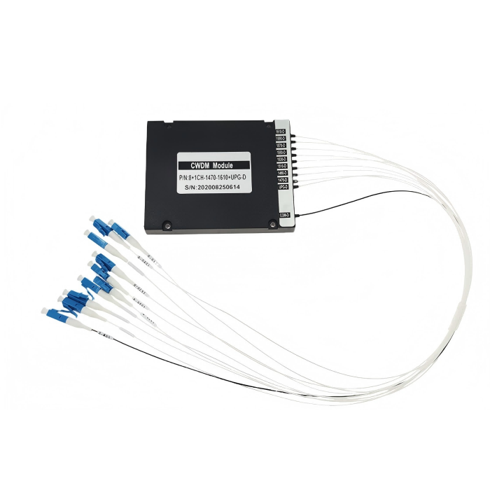
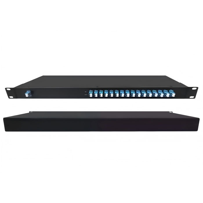
Feiyi’s CWDM ordering information includes ABS-box options, LGX formats, 19-inch 1U rack arrangements and customized module types. Fiber construction can be 900-micron loose tube, 2.0 mm or 3.0 mm cable, while listed lead lengths include 0.5 m, 1.0 m and 1.5 m with customization available.
An embedded ABS module needs a different handoff from a rack-mounted unit
An OEM using an ABS module often needs the fiber leads to reach internal splice points or adapters without excess bending. The drawing should show where the module sits and how the leads exit. A network operator using a rackmount assembly instead cares about front-panel labeling, adapter type and service access.
Feiyi’s published CWDM package choices include 100 x 80 x 10 mm, 120 x 80 x 18 mm and 140 x 115 x 18 mm ABS formats, plus LGX and 1U options in the ordering information. A buyer should not allow packaging to be substituted informally after the optical sample is approved, because installation fit is part of the product configuration.
Connector polish and family must match the patching environment
Feiyi’s ordering options include LC/UPC, LC/APC, SC/UPC, SC/APC, FC/UPC and FC/APC. A network already built around LC/UPC patch panels should not receive LC/APC simply because an angled polish appears attractive on paper. Mating interfaces must be compatible.
For a distributor, connector type is also an inventory dimension. Stocking “8CH CWDM” without recording connector polish can create an apparent replacement that cannot be installed. The item description should keep channel plan, Mux/Demux configuration, package and connectors together.
Distributor stocking is easier when the CWDM MUX DEMUX supplier separates optical and mechanical variants
A distributor serving several integrators can reduce duplicate inventory by treating the wavelength map as the first classification layer and package/connector as the second. For example, two 8-channel assemblies may share the same wavelengths but differ because one is an ABS module with bare leads and another is a 1U rack with front-panel LC adapters.
Stock the configurations that repeat; configure project-specific interfaces separately
The 4CH, 8CH and 16CH Feiyi products provide natural base families. Where customers repeatedly use one channel plan, that can become a stocked optical configuration. Less common connector or enclosure combinations can then be ordered against specific project drawings rather than creating many nearly identical shelf items.
This approach also makes replacement easier. A technician can match the wavelength plan first, then confirm connector and enclosure. It reduces the risk of selecting by product photograph, which is unreliable when passive modules share similar housings.
Incoming checks should follow the same route map used to select the supplier
At receiving, confirm the unit label, wavelength list, common port and channel ports before measuring loss. Clean connector end faces, use the agreed wavelength source, and record the channel identity with each result. For a multi-channel unit, compare the measured paths with the link-budget limits approved for that project.
If the order includes a Mux and Demux pair, verify both directions as separate assemblies. If it includes an OADM, check the drop, add and express behavior specified for the node. If it uses a rackmount version, verify front-panel labels before installation.
Useful Feiyi references include the 4CH CWDM Mux Demux, 8CH CWDM Mux Demux, 16CH CWDM Mux Demux, CWDM Mux Demux in 1U Rackmount, CWDM OADM Module and the WDM product range.
For a new order, the most useful document to send the supplier is a one-page wavelength route: active channels, reserved channels, common port, Mux or Demux direction, package, connector type and the loss/isolation limits from the link design. That gives the supplier enough information to build the intended CWDM assembly without turning the RFQ into a generic catalog request.
Reserve wavelengths should be documented even when they are dark on day one
A phased CWDM project often installs a larger passive module before every service wavelength is active. In that case, the site record should distinguish live, reserved and intentionally unused ports. Cap and protect the unused adapters, keep their wavelengths in the channel plan, and avoid using them as convenient parking positions for unrelated jumpers. When a later service is activated, the installer can then trace the reserved wavelength without reopening the original design question. This is particularly useful for an 8CH or 16CH build deployed with only part of its capacity in service.