A Polarization Maintaining Optical Components Manufacturer Must Match the Whole Instrument Chain
Five individually acceptable optical parts can still make an unacceptable instrument. If a laser source, isolator, wavelength filter, circulator and connector lead use different polarization conventions, the finished path may lose the state that the detector needs. Evaluating a polarization maintaining optical components manufacturer therefore starts with compatibility across the assembly. For a 1550 nm sensor or laboratory instrument, begin with Feiyi’s PM 1550 nm circulator and PM 1310/1550 nm isolator, then define wavelength, propagation direction and working axis for every interface.
Feiyi offers several parts needed for that discussion, including PM jumpers, filter WDMs and inline polarizers. That range gives an OEM purchasing engineer meaningful options to evaluate together. It does not make every combination interchangeable. Before comparing unit prices or approving a consolidated order, draw the optical chain and mark the condition under which each component’s stated performance applies.
A polarization maintaining optical components manufacturer should review one complete optical route
Consider a sensor OEM assembling a source-protection branch, a shared outgoing and returning fiber, and a separate receiver. The PM isolator belongs where reverse transmission should be suppressed; the PM circulator belongs where returned light must reach another port. Treating both as interchangeable protection devices would change the sensor’s route, even if their housings looked similar. A manufacturing evaluation should establish whether the proposed combination preserves the required path as well as its polarization reference.
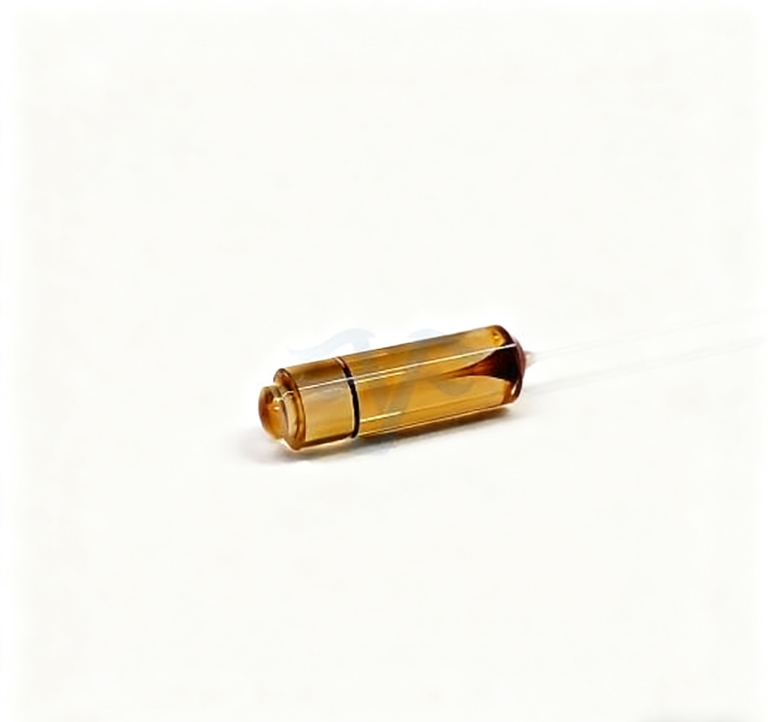
The Feiyi PM circulator states a Port 1-to-Port 2-to-Port 3 configuration, PM1550 fiber and a 1550 ±30 nm operating band. Its minimum listed extinction ratio is 20 dB. The PM isolator specifies slow-axis operation with fast-axis cutoff and separate 1310 or 1550 ±10 nm versions. These are component-specific facts. A signal within the circulator’s band is not automatically within the narrower isolator band, and an axis accepted by one part may be rejected by another.
Slow-axis isolation must agree with the PM1550 jumper ends
Feiyi’s PM 1550 nm optical patch cord lists fast-axis, slow-axis or customized orientation. The buyer should choose the orientation that actually interfaces with the isolator, rather than copying a fast-axis option because it appears elsewhere in the assembly. The drawing should identify the connector key and viewing direction at both ends so that a correct fiber orientation is not described from two incompatible perspectives.
A second scenario is a purchasing engineer replacing only the jumper after a cable-length change. The optical component numbers remain unchanged, but the new lead arrives with a different axis convention. A low insertion-loss check might accept it while the assembled polarization performance deteriorates. Freeze the axis requirement with the optical component references, not just with the cable purchasing description.
PM component specifications describe different jobs within the instrument
Insertion loss, isolation, extinction ratio and return loss answer different questions. The PM isolator’s isolation concerns unwanted reverse transmission. The circulator’s directional routing separates the return path. The jumper’s extinction ratio concerns polarization preservation through its specified interface. None of those values can stand in for the other measurements, and adding extinction ratios together does not produce a defensible chain specification.
The published PM1550 jumper entry gives a minimum extinction ratio of 22 dB and insertion loss no greater than 0.2 dB in its connector table. The PM isolator separates P and A grades and single-stage from dual-stage options. A P-grade single-stage unit lists maximum insertion loss of 0.65 dB; a dual-stage P-grade unit also lists 0.65 dB while specifying different isolation. Keep the grade and stage attached to the value when preparing a component comparison.
A PM inline polarizer changes the accepted state, rather than repairing every upstream defect
The PM 1550 nm inline polarizer specifies slow-axis transmission and fast-axis cutoff. It lists SM-28E or PM1550 input/output fiber choices. That distinction matters when connecting a source whose state is not yet aligned to the PM chain. A polarizer can select a state, but rejected optical power is not recovered simply because the downstream extinction ratio becomes better.
For this polarizer, Feiyi lists a 1550 ±50 nm operating range, typical insertion loss of 0.3 dB and maximum insertion loss of 0.5 dB. Those figures describe the selected device under the applicable conditions. A misaligned source can incur additional system loss. If the instrument cannot tolerate that lost power, the purchasing decision must return to the source interface or alignment method; a higher polarizer specification alone is not a solution.

The filter WDM adds a wavelength map to the PM-axis map
Feiyi’s polarization-maintaining filter WDM offers band combinations including a 1520–1580 nm pass channel with a 960–990 nm reflection channel. Another listed combination pairs the telecom pass band with a 1020–1080 nm reflection band. These are distinct optical arrangements. A request saying only “1550 nm PM WDM” leaves the reflected channel and port assignment unresolved.
The filter WDM lists insertion loss no greater than 0.8 dB for pass and reflection channels and a minimum extinction ratio of 18 dB. Its ordering information includes fiber, connector and lead-length choices. If the filter joins a PM1550 signal and another wavelength, identify which fiber type is used on each physical port. Do not infer one fiber’s operating suitability for every wavelength merely from the common package name.
AFW’s PM filter WDM documentation provides independent background on wavelength-selective filtering with polarization-maintaining interfaces. Its specifications belong to AFW products. For the Feiyi assembly, keep the confirmed Feiyi pass/reflection map and axis drawing as the controlling documents.
The PM manufacturing order needs an assembled power limit, not the largest catalog number
The selected 1550 nm PM circulator lists maximum power handling of 300 mW, while the PM1310/1550 isolator lists 500 mW. The inline polarizer has separately selectable power entries from 0.3 W through 10 W. A 10 W polarizer option does not turn a chain containing the 300 mW circulator into a 10 W chain. Determine the power arriving at each device before selecting a rating.
A source-protection stage may see almost the full launch power while a returned sensor signal is much weaker. A WDM reflection port may carry a different optical power again. The drawing should therefore contain a power value or expected range on each route. Where pulsed sources, startup transients or connector power density matter, seek device-specific confirmation; an average-power entry does not establish every pulse condition.
Polarizer power options and circulator packaging belong to separate approval decisions
The PM polarizer lists cylindrical package choices including 5.5 mm diameter by 35 or 50 mm length. The circulator also lists cylindrical packages and a 90 ×20 ×10 mm ABS option. Similar dimensions do not prove that the internals, leads or allowable mount loads are the same. A mechanical drawing should show how each selected housing is retained and where the fiber transitions receive strain relief.
For a compact instrument, ask whether the desired power-rated polarizer uses the same approved housing as the lower-power version. That is a configuration question, not a promise that every option fits one envelope. Protect the chain’s weakest mechanical interface during shipment and installation: a supported package with loose, identified lead loops is more useful than an unidentified bundle of parts whose fiber exits can be loaded during unpacking.
PM instrument acceptance should separate device evidence from integration evidence
Device conditions and assembled conditions need separate approval. The selected PM isolator lists −20 to +75 °C operation, while the PM filter WDM lists 0 to +75 °C. A cabinet expected to start below zero cannot be accepted merely because the isolator supports that condition. Identify every device exposed to the cabinet environment, and resolve the narrower interval. Storage-temperature limits remain separate: surviving transport at a low temperature does not establish optical performance while operating there.
Start incoming checks with identities: wavelength version, grade or stage, fiber type, connector finish and axis drawing revision. For the circulator, verify the intended forward routes and the leakage route relevant to the receiver. For the isolator, distinguish forward loss from reverse isolation. For the polarizer, identify the passed state. A single “optical loss passed” record would leave the reasons for selecting these different devices untested.
Then evaluate the assembled chain with a defined input state and the actual jumper routing. Preserve the source condition, connector orientation and detector reference plane in the test record. This lets the engineer distinguish a changed device from an altered test setup. It also gives the manufacturer a useful basis for discussing a discrepancy without assuming that a favorable individual-device result proves finished-instrument performance.
For the inline polarizer, compare loss and extinction ratio under the same stated launch condition rather than selecting whichever setup gives the better number for each. For the filter WDM, retain the tested wavelength and channel route. For the circulator, identify which port was illuminated and which output was measured. Those identifiers make each result usable in the assembled sensor. Without them, a report can contain valid measurements that answer different optical questions from the instrument’s requirement.
The PM1550 jumper should also be assessed in the mounting route intended for the instrument. A clean, straight bench lead and the same lead routed around a housing are different mechanical conditions. Do not invent a bend tolerance from the fiber-family name. Agree the allowed routing geometry for the selected cable style, then preserve it while checking the finished path. This is especially useful when the OEM changes enclosure size without changing the optical bill of materials.
If one chain result misses its limit, isolate the relevant interfaces before rejecting every supplied part. A low receiver signal can follow a misassigned WDM port; poor polarization can follow an axis mismatch; unexpected source feedback can follow an isolator orientation problem. Testing the actual failure route lets the manufacturing discussion focus on a specific component or integration decision instead of requesting a higher specification for an unrelated parameter.
OZ Optics’ PM patch-cord guidance explains why connector axis alignment is important. Fujikura’s PM fiber overview describes PM fibers for polarization-sensitive applications. These technical principles support preserving an explicit axis reference; they do not authenticate a particular Feiyi sample or substitute for its acceptance results.
When a supplier proposes a substitution, ask which chain assumptions it changes. Replacing a single-stage isolator with a dual-stage version affects isolation requirements and potentially the available loss margin. Replacing a polarizer with an SM-fiber version changes how the state enters or leaves that device. Replacing a WDM with another wavelength combination changes a physical port’s task. A compatible substitution must preserve the relevant route, not merely carry the same general family name.
Feiyi’s discussion of why polarization-maintaining components matter is useful for the broader system context. For the purchase itself, keep a narrower deliverable: one selected bill of materials tied to one wavelength map, one axis convention and one assembled test definition.
Release that component set when the engineer can point to the limiting device on every powered route and to the polarization reference at every detachable connection. If either answer is missing, resolve the specific interface before changing the entire range or increasing the order quantity. The best next sample is the one that tests the remaining incompatibility in your instrument.