Buying From a PM Variable Optical Attenuator Supplier When the Detector Has Too Much Light
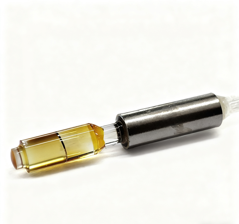
A detector that receives too much light at one source setting can still need every available fraction of a weak signal at another. The attenuation component must serve both conditions. When comparing a PM variable optical attenuator supplier, begin with the wavelength, power entering the attenuator and usable detector range, then check the loss that remains at the attenuator’s minimum setting. Feiyi’s 1310/1550 nm PM inline VOA and 780 nm PM inline VOA are relevant starting points for polarization-sensitive instruments. Their adjustable loss reduces transmitted power; it does not amplify a weak return or automatically regulate a changing source.
The PM variable optical attenuator’s minimum loss belongs in the weak-signal budget
Feiyi’s PM inline attenuator listings specify an attenuation range of 0.6–60 dB and insertion loss no greater than 0.6 dB under the stated connector-free conditions. A buyer interested only in the 60 dB end may miss the other end of the operating problem. The device remains in the optical path when the source is reduced or the returned signal becomes small.
Minimum PM VOA attenuation is not an optical bypass
A minimum setting with finite loss cannot be treated as a lossless connection. Include the selected device, connectors and other components in the lowest-signal budget. If the detector barely reaches its useful measurement range without the attenuator, adding one may require a different source condition or architecture. The adjustment screw cannot recover light already lost in the component or its interfaces.
Imagine a sensor development team using attenuation to keep a strong reference within the detector’s range. The same instrument later measures a weaker optical return. If the attenuator stays in that return path, the engineer must check the low-signal condition as well as the high-signal condition. Purchasing should describe where the component sits, rather than ordering the largest attenuation range and assuming it solves both extremes.
Thorlabs’ PM inline VOA documentation explains manual power balancing and dynamic-range evaluation. That general use supports this application, while Feiyi’s own specification defines the selected attenuation range, wavelength and interface. Another manufacturer’s resolution or optical power rating should not become a promise for this device.
Calculate the detector power before setting a PM variable optical attenuator
Attenuation in decibels relates input and output optical power: an ideal attenuation of A dB gives an output-to-input ratio of 10−A/10. This is a calculation, not a Feiyi test result. It helps translate the detector’s accepted power range into a proposed setting, but the completed path still needs a measurement at the detector plane.
Calculated example, not a device guarantee: 10 mW entering an ideal 20 dB attenuation becomes 0.1 mW before accounting for other path losses. A 30 dB attenuation would reduce the same input to 0.01 mW. The correct setting depends on the actual detector and measurement requirement.
PM VOA input-power approval remains necessary when detector power is low
The Feiyi PM inline VOA tables list maximum optical power of 300 mW. A low expected detector power after attenuation does not permit a higher, unapproved input power at the attenuator. State the maximum incident power and operating mode where the component is installed. For pulsed or amplified light, obtain the application-specific confirmation needed for the exact device; a milliwatt entry is not an undocumented peak-power damage specification.
For a receiver test, specify whether the useful power reference is at the attenuator output connector or at the receiver input after an additional jumper. Those are different reference planes. A long chain of adapters can make a setting that appears appropriate at the VOA output unsuitable at the detector. Keep the measurement location attached to the reported power.
Also establish whether the reported attenuation is total path loss or added loss above a minimum-setting reference. Counting a minimum insertion loss twice can make the calculated detector level unnecessarily pessimistic; omitting it can do the opposite. Use one definition consistently for the selected delivered PM VOA.
OZ Optics’ variable-attenuator technical document identifies receiver padding and power balancing as general applications. It does not establish the attenuation mechanism, power capacity or calibration accuracy of the Feiyi component. The order should request confirmation of the selected construction and operating limits rather than infer them from its external appearance.
Choose the PM attenuation wavelength and fiber before approving a connector
The 780 nm PM VOA lists 780 nm operation with a ±50 nm operating-bandwidth entry, PM780-HP or other fiber options and a 26 ×18 ×8 mm housing. Feiyi’s other PM inline VOA listing identifies 1310 and 1550 nm operation, with PM1310 and PM1550 appearing in its ordering information. The telecom variant’s table and ordering fiber entries should be reconciled in the accepted specification before the sample is released.
A 780 nm PM attenuator should not inherit a 1550 nm test setting
Different wavelength variants require their own appropriate fiber and optical-power measurement conditions. An attenuation position established at 1550 nm is not proof of the same transmitted power at 780 nm. Select the product against the actual source spectrum and confirm the applicable wavelength-dependent behavior. The catalog’s bandwidth entry should not be converted into an assumption of identical attenuation at every wavelength within it.
The Feiyi single-mode variable attenuator is an alternative when the optical circuit does not require a maintained polarization axis. Its table separates HI780, HI1060 and SMF-28E routes and their wavelength ranges. A buyer should choose that family for its actual application, rather than substitute it into a PM circuit merely because its housing dimensions and adjustment method are similar.

The PM inline VOA defaults to slow-axis alignment with the connector key according to its notes. Confirm that reference against the adjoining components. Feiyi’s PM1550 patch cord provides a relevant external connection for a 1550 nm setup, but its connector and axis must match the accepted attenuation assembly. Connector style alone does not prove alignment.
The 780 nm PM VOA’s enclosure temperature is part of the operating condition
The 780 nm listing gives an operating range of 0 to +70°C and a storage range of −40 to +85°C. Storage tolerance does not establish operation below 0°C. If the attenuator sits inside an instrument enclosure, evaluate its local environment rather than only the room temperature around the complete instrument. A source or drive board nearby can change that condition. For use beyond the listed operating range, request an explicitly approved variant instead of assuming that a stored component is also qualified to measure light there.
Connectorized PM VOA acceptance differs from the bare-fiber figure
Feiyi states that its listed PM VOA data exclude connectors and were measured in a 25°C environment. Its notes specify a 0.3 dB insertion-loss increase, 5 dB return-loss decrease and 2 dB extinction-ratio decrease when connectors are added. These are published comparison conditions; the final purchase specification should identify the actual delivered assembly and how its performance will be accepted.
PM extinction ratio must remain acceptable across the useful attenuation settings
The listed extinction ratio of at least 18 dB describes the polarization requirement under the documented condition. It is separate from the attenuation range. A component can reduce optical power to the desired level while an unsuitable interface degrades the polarization condition. Ask for acceptance points at the settings the instrument will actually use, including the selected connectors and axis reference.
A prototype team that begins with bare fibers and later adds FC/APC ends should reopen the link budget and test boundary. The added interfaces can change the measured loss, return loss and extinction ratio. Keep the source launch, power-meter wavelength setting and PM test connections consistent so that a construction change is not confused with an unexplained adjustment error.
If the source also requires reverse-feedback protection, Feiyi’s PM 1310/1550 nm isolator is a relevant separate component to review. A VOA reduces transmitted power; it is not an isolator that provides the selected reverse-protection behavior. Include the isolator’s forward loss in the complete power budget instead of expecting the attenuation setting to represent the entire chain.
A manually adjusted PM attenuator does not hold constant detector power by itself
The Feiyi inline component is shown with a mechanical adjustment. Its product information does not establish a built-in power meter, automatic feedback loop or remotely commanded attenuation control. If the source drifts while the attenuator remains at one position, the output power can change. Define whether the instrument needs an occasional manual setting or active regulation before choosing the component.
Keysight’s optical-attenuator information distinguishes attenuation setting from output-power setting in an instrument with power measurement. That distinction is useful when defining the required function. It does not mean a manual Feiyi VOA includes those instrument capabilities.
A laboratory fixture adjusted once for a stable source can have a different requirement from a production station that cycles through several power levels automatically. The former may be served by a suitably approved manual component. The latter needs a defined control method, repeatable setting process and reference measurement. Avoid asking purchasing to solve an automation requirement with an undocumented manual-dial calibration.
EXFO’s attenuation application note discusses wavelength-specific calibration and the distinction between attenuation and power control. Use that background to identify the required measurement reference. A setting found at one wavelength or in one connection arrangement should not be treated as a universal calibrated power value.
Make the PM VOA setting accessible without moving its fiber exits
The listed 26 ×18 ×8 mm package fits a compact assembly, but the instrument designer must reserve room for the adjustment and the fiber exits. Do not place the screw where reaching it forces a PM lead to twist or makes a connector bear the mechanical load. Identify the intended mounting arrangement and usable access in the prototype before confirming the delivered lead lengths.
For receiving, request protection that keeps the adjustment body from pressing against its own fiber leads, with connector caps appropriate to the selected terminations. Ask how the component and its accepted configuration will be identified during packing. These are proposed handling controls for a compact attenuator, not an assertion of a particular Feiyi carton or shipping practice.
A distributor carrying both 780 nm and telecom PM VOAs should keep wavelength, fiber and connector-axis details in the stock description. Record any accepted attenuation setting as a test condition, not as a substitute for the product identity. If a customer replaces a device, re-establish the detector-plane power with the new assembly instead of assuming the previous screw position produces the same result.
Before approving the PM VOA, resolve two numbers with the engineer: the highest permitted power at its input and the lowest useful signal at the detector after all minimum losses. Then confirm the wavelength, PM interface and settings that connect those two limits. If the design requires automatic power holding, define that control function separately; a wide attenuation range is not evidence that it is already present.
Feiyi’s PM variable-attenuator overview provides further background on the component family. Keep the actual detector-plane measurement and selected delivered interfaces alongside that overview when approving the attenuator for the instrument.