A Fiber Polarization Beam Splitter Supplier Should Define Both Receiver Channels
A receiver that measures two polarization branches needs more than two labeled fiber leads. It needs to know which optical state each detector receives, what leakage reaches the other detector and how the two path losses differ. A fiber polarization beam splitter supplier should define those channels before the receiver is calibrated. Begin with Feiyi’s 1550 nm 2×2 polarization beam combiner/splitter or its 1550 nm 1×2 version, according to the required port topology. Confirm the channel map and analyzed polarization references first.
For an optical measurement instrument, separating polarization states is a different task from taking a fixed percentage of total power. A 50/50 coupler is not a substitute simply because it has two outputs. The receiver designer should identify the two states to be measured and the reference plane at which the splitter’s performance becomes part of the instrument calibration.
A fiber polarization beam splitter supplier should label the measured states, not only the leads
Consider an instrument that routes two orthogonal components of an incoming signal to two detectors. Channel A and Channel B need stable definitions in the electrical measurement software as well as on the optical drawing. A swapped fiber connection changes that definition, even if both detectors continue to register light. The splitter order should connect the physical port identifiers to the intended analyzed states so an installer can preserve the measurement meaning.
Feiyi’s 1550 nm 2×2 product lists a 1550 ±40 nm band, typical insertion loss of 0.6 dB and maximum insertion loss of 1.0 dB. It lists a minimum extinction ratio of 20 dB at 23 °C for the PM fiber configuration. These entries describe a candidate component. They do not establish the instrument’s channel identity or tell you which four-port route the loss measurement uses. Request the approved route diagram for the supplied version.
A 2×2 polarization splitter needs a four-port map before receiver calibration
The product describes SM-28E or PM1550-XP input/output fiber options and uses working-axis wording that requires configuration-specific interpretation. Do not turn that short description into a guessed port map. Identify each input, each selected output and any unused route. State the fiber type and polarization reference for each lead, particularly if one connection is single-mode and another is polarization maintaining.
A service engineer replacing an installed 1×2 splitter with a 2×2 unit should not simply connect the three familiar leads and ignore the fourth. The topology change needs a routing review, including how the unused interface is handled and whether the original channel calibration still applies. This is a specific replacement decision; a larger port count does not establish compatibility with a smaller instrument layout.
Polarization splitter extinction and receiver gain imbalance are separate errors
Extinction ratio concerns separation between intended and unwanted polarization contributions under the stated test. Receiver gain imbalance concerns the different response of the two complete detection channels. Loss in a fiber lead or a different detector responsivity can change that imbalance even when the splitter’s polarization separation is acceptable. Keep the component’s optical limit separate from the instrument’s calibration correction.
| Observed channel behavior | First interface to examine | Record needed to interpret it |
|---|---|---|
| Both detectors respond to a defined input state | Polarization splitter routes and launch reference | Which state was launched and which outputs were analyzed |
| One branch is consistently weaker | Splitter path, connector lead and detector chain | Loss and detector response at defined reference planes |
| Channel identity changes after replacement | Physical port-to-detector map | Approved route labels and installed connection record |
Do not use equal detector readings as proof that the splitter is performing an equal-power split. An incoming state can contain unequal powers in the two analyzed components, and the detectors can have different responses. An optical receiver needs a controlled input condition to interpret those readings. The order should define the optical measurement conditions rather than specifying that the two detectors must always agree.
Channel loss correction cannot remove unwanted polarization leakage
A software gain correction may compensate a known channel attenuation under its calibration conditions. It does not make unwanted polarization leakage disappear from the other detector. Likewise, selecting a splitter with better stated extinction does not correct an incorrectly assigned port. The engineer should evaluate loss, leakage and labeling as three separate issues, with the relevant input condition recorded for each.
OZ Optics’ polarization-measurement note explains the importance of launch alignment and analyzed states. Thorlabs’ polarizing-beamsplitter description provides background on orthogonal separation. These are technical explanations of the measurement principle; they do not provide calibration data for a Feiyi receiver assembly or establish a complete polarization-analysis instrument.
The 1310 and 1064 nm splitter alternatives need their own acceptance limits
Feiyi’s 1310 nm 2×2 version lists a ±40 nm band, 0.4 dB typical insertion loss, 0.6 dB maximum insertion loss and a minimum extinction-ratio entry of 22 dB at 23 °C. Its fiber choices include SM-28E and PM1300-XP. These differ from the 1550 nm 2×2 loss and extinction entries. Do not copy the 1310 nm acceptance limits into the telecom receiver merely because the package topology matches.
The 1064 nm 2×2 product lists ±20 nm, 0.6/1.0 dB typical/maximum loss and a 20 dB minimum extinction-ratio entry. The listed PM980 fiber option needs selection for the actual build. A nominal 1064 nm instrument with tuning or broad source output should define its required interval before accepting that component’s narrower band.
A wavelength change should reopen the receiver’s optical reference
Suppose the instrument team develops a second receiver version at 1310 nm. It cannot preserve the 1550 nm optical calibration merely by changing the splitter label. The selected splitter, fiber leads and detector response all belong to the new wavelength. Keep the original electrical channel identities if that is useful, but establish the new optical routes and loss conditions instead of representing the earlier calibration as transferable evidence.
The 1550 nm 1×2 product offers another topology with a listed 0.4 dB typical and 0.6 dB maximum loss and a 22 dB minimum extinction-ratio entry. Compare it when the receiver requires its three-port arrangement. The decision should follow the needed optical route and approved axes, not an assumption that the lowest maximum-loss number identifies the right topology for every receiver.

PM1550 detector leads preserve a reference only when their ends agree
Feiyi’s PM1550 optical patch cord specifies PM1550 fiber and fast-axis, slow-axis or customized direction options. Match the selected orientation to the splitter output and receiving interface. The jumper’s 22 dB minimum extinction-ratio entry cannot establish the complete receiver’s performance if the launch or detector connection uses another reference.
An assembly technician replacing a damaged lead needs the axis definition, connector finish and endpoint identity, not only its length. If the replacement moves a detector connection from one axis reference to another, the instrument can display a changed polarization result while ordinary continuity remains correct. Put endpoint and orientation information into the lead description so a service replacement preserves the intended receiver channel.
APC and PC connector choices should follow the mating receiver interface
The splitter ordering options include FC/PC, FC/APC, SC/PC and SC/APC. Select the finish that mates with the installed connection. A connector family name alone does not authorize mixing different polished interfaces. Define whether the acceptance loss is measured through the delivered connector pair or at another plane; otherwise the replacement can be compared with a test that excluded the new connection.
For a compact receiver, agree the lead length and support route before calibration. The splitter lists at least one meter at each end, while ordering choices include other specified lengths. Resolve the supplied length on the final drawing rather than assuming that every ordering option and headline entry describe the same unit. Preserve enough identification to distinguish two physically similar detector leads after they leave the package.
Approve polarization splitter channels before closing the receiver housing
Use an input whose state and wavelength are known for the selected test. Measure each required route and record the output identifier, analyzed state and detector reference. Test the unwanted contribution where it matters to the receiver. The aim is a usable channel definition, not a claimed completed laboratory result. If the input is uncontrolled, the engineer cannot confidently assign a change to the splitter’s leakage behavior.
Then examine the assembled receiver with its actual PM leads and chosen detector arrangement. A standalone splitter pass does not cover a later port swap or connector orientation change. Keep component acceptance results and receiver calibration together but distinguish their scopes. That gives maintenance staff a way to decide whether a replacement requires only an interface check or a broader recalibration.
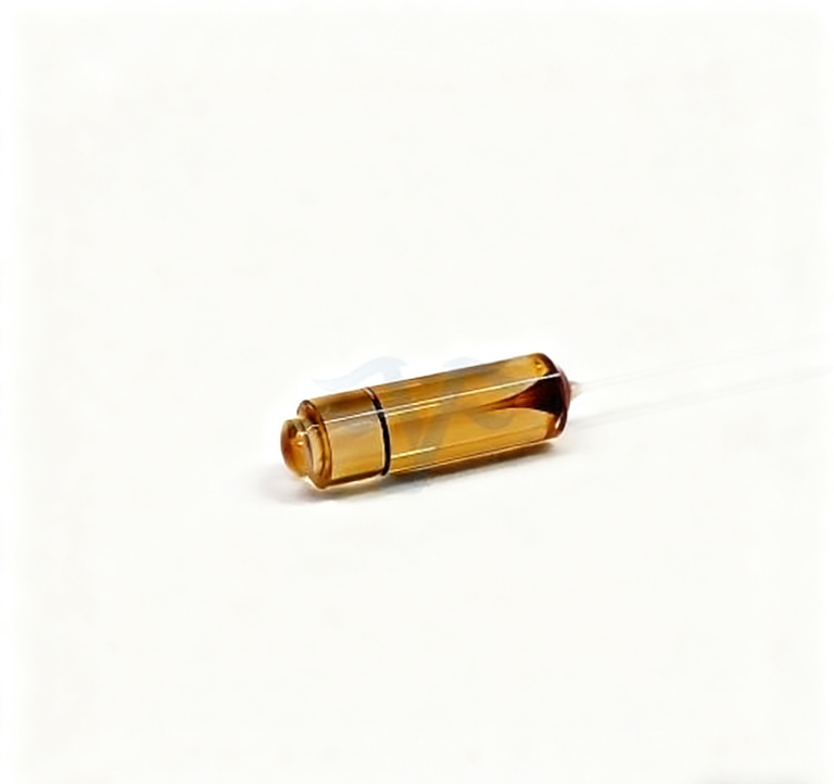
The 2×2 products list block-like package dimensions of 14 ×12 ×8 mm or 12 ×12 ×10 mm. Confirm the selected mechanical envelope and fiber exits before fixing the receiver mount. Ask for the actual port labels to remain readable during installation and for protection that avoids loads on the lead exits during unpacking. Those requirements should be agreed for the ordered device rather than inferred from the photograph.
The 1550 nm 2×2 device lists selectable power options from 0.3 W to 10 W. The receiver’s low electrical signal does not prove that the splitter sees a low optical input, especially when a strong source is present before attenuation or detection. Specify the incident optical condition at the splitter and the approved power configuration. Confirm any pulse conditions separately; the selectable power row should not be turned into an unqualified peak-power statement.
Two intensity channels do not by themselves establish a complete measurement of every polarization property. They give the instrument the two projections defined by its optical arrangement. If the project requires additional phase-sensitive information or a more complete polarization analysis, its architecture needs the appropriate additional elements and calibration. Do not ask a two-output fiber splitter to provide an instrument function that the detector arrangement never measures.
For a service replacement, retain one controlled comparison of the old and new channel assignments using the instrument’s defined input. If the two detectors exchange their interpreted states, first examine port labeling and PM lead references. If the labels agree but their responses differ, separate detector-chain changes from optical-path changes. This prevents a receiver gain adjustment from concealing a swapped optical interface and preserves a meaningful record for the next replacement.
AFW’s fiber combiner/splitter information gives another reference for port-specific configuration. Feiyi’s PM beam combiner and splitter discussion covers the wider family. Keep the receiving decision anchored to your selected topology, wavelength and two defined measurement channels.
Close the receiver housing when each optical output has an unambiguous detector assignment and the calibration record names the tested state and interface. If one branch behaves unexpectedly, inspect its actual route before requesting an arbitrary higher extinction ratio. The useful splitter is the one whose two channels retain the meaning your instrument is supposed to measure.