Approve the Passed Axis With a PM Inline Polarizer Manufacturer Before Protecting the Source
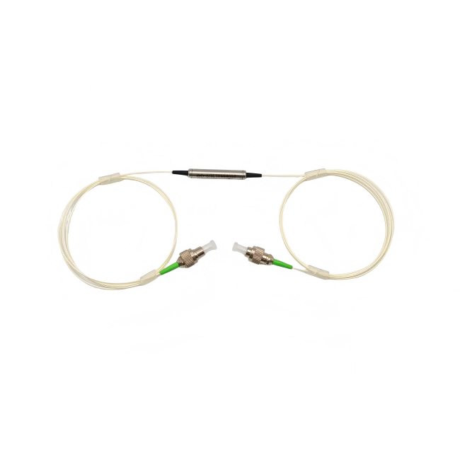
A polarizer with a strong extinction-ratio figure is not automatically a source-protection isolator. If the purchasing description confuses those functions, the instrument can lose wanted power while retaining an unwanted reverse path. A PM inline polarizer manufacturer should first confirm the polarization you intend to pass, the wavelength and the fiber at each end. Feiyi’s 1550 nm inline polarizer and 1310 nm version specify slow-axis operation with fast-axis cutoff. Start there when your requirement is polarization selection.
For an OEM laser assembly, that means separating two questions: which state should reach the next optical element, and which reverse light should be prevented from reaching the source? The inline polarizer answers the first under its specified configuration. Feiyi’s PM fiber isolator is a different family to evaluate for directional source protection. Draw both functions if the assembly needs both.
A PM inline polarizer manufacturer should identify the passed state at both fiber ends
The Feiyi 1550 nm polarizer lists SM-28E or PM1550 input/output fiber choices. That is an important configuration decision. A single-mode input can carry a changing state of polarization; a PM output needs a defined relationship to the polarizer’s passed axis. Asking for a PM product name without assigning those interfaces leaves the source launch and output reference unclear.
Consider an instrument with an ordinary single-mode source lead feeding a polarization-sensitive stage. An SM-input, PM-output configuration may be a relevant request, but the supplier should confirm the actual supplied construction. The polarizer selects a component of the incoming field; it does not ensure that an uncontrolled source always places the same power in that selected component. Define the launch condition and allowable power variation alongside the axis requirement.
Slow-axis transmission requires a connector reference, not just a fiber label
The polarizer’s slow-axis operating statement needs to be connected to the delivered termination. If the output is connectorized, agree how the key relates to the passed PM axis and which viewing direction defines that relationship. If the output is bare fiber, agree how the axis is identified at the assembly joint. A statement that the output uses PM fiber does not itself establish either reference.
A purchasing engineer specifying an inline polarizer for a replacement module should preserve that reference even when the connector form changes. An FC-to-SC modification may alter the mechanical interface while the useful optical state remains the same. Review both requirements on the replacement drawing rather than accepting a connector conversion as proof that the axis stayed compatible.
PM polarizer loss depends on the wanted input state
Feiyi lists a 1550 ±50 nm band, typical insertion loss of 0.3 dB and maximum insertion loss of 0.5 dB for the 1550 nm polarizer. The 1310 nm version lists 1310 ±50 nm and the same typical/maximum loss entries. These figures should be interpreted for the intended transmitted state and supplied configuration. They do not mean that all polarization states entering the device experience the same small loss.
If the launch is misaligned to the passed state, some incoming power belongs to the rejected state. That loss of useful transmitted power can occur even when the component itself is performing correctly. A low-loss device specification cannot repair a source that launches the wrong state. The engineer should distinguish component transmission from the projection of the input onto the selected polarization.
Can a polarizer stabilize power from an uncontrolled SM source?
A polarizer alone does not turn every varying input state into constant transmitted power. For a source whose state changes, the power projected onto the passed axis can also change. If the receiving instrument requires both a stable state and stable optical power, define how the source condition is controlled or monitored. Do not specify a larger polarizer power rating as a substitute for controlling that input.
OZ Optics’ SM-input/PM-output polarizer example illustrates that fiber-end construction is a real configuration distinction. Its performance belongs to that device. For Feiyi, confirm the requested fiber arrangement and passed-state reference before attaching any acceptance value to the assembled source route.
The 780 and 1064 nm polarizers have their own loss and extinction entries
The 780 nm inline polarizer lists a ±30 nm band, typical loss of 0.6 dB, maximum loss of 1.0 dB and a minimum extinction ratio of 25 dB at 23 °C for the PM fiber configuration. The telecom versions list a 28 dB minimum entry. Carry these differences into the purchasing limits instead of treating the wavelength variants as one performance line.
The 1064 nm polarizer lists ±30 nm, 0.3 dB typical loss, 0.5 dB maximum loss and a 28 dB minimum extinction-ratio entry. Its ordering choices identify PM980 or PM1060 among fiber options. Ask which fiber and termination correspond to the chosen configuration; do not resolve a short general fiber description by assuming every option has the same behavior.
A 780 nm laboratory route should not inherit the 1550 nm acceptance limit
A laboratory purchaser adapting a telecom instrument layout to 780 nm may retain the same physical space and source-control concept. The optical acceptance still changes with the selected version. The 780 nm polarizer’s higher listed loss and different minimum extinction ratio matter to the receiving power and state requirements. Select it using its own limits, then confirm that the instrument has enough useful power under its actual launch condition.
The product identifies 780-HPE or PM780 in its fiber information, with additional ordering choices. Preserve the approved fiber designation and connector finish in the order. A similar-looking connectorized package does not prove that the lead is intended for the same band or the same polarization reference as an existing telecom unit.
For either wavelength family, determine whether the stated extinction value is being used at its specified temperature and measurement condition. A device entry stated at 23 °C is not by itself a complete extinction guarantee across the entire operating-temperature range. The receiving specification should state the condition actually needed and obtain confirmation where the project requires a broader limit.
An inline polarizer cannot replace directional isolation
A second buyer scenario is a laser-equipment purchaser replacing an isolator with a polarizer because both appear to suppress unwanted light. A polarizer selects polarization; an isolator is selected for nonreciprocal source protection. Reverse light having a transmitted polarization is not automatically rejected by the polarizer. The purchasing description should identify the reverse-path requirement explicitly rather than inferring it from a front-page “high isolation” phrase.
The Feiyi PM1310/1550 isolator lists single-stage and dual-stage variants with isolation values and slow-axis operation. That makes it a separate candidate for the directional job. The choice between its stages belongs to the required reverse suppression and available loss budget, while the inline polarizer selection belongs to the state that the instrument should transmit. Those two approvals should not be merged into a single extinction-ratio number.

Would a higher extinction ratio fix laser back-reflection?
Not if the unwanted return occupies a polarization the polarizer transmits. Diagnose the return route and the source’s protection requirement before changing the polarizer. A better passed/rejected-state ratio does not establish an isolation value for that return. Where both functions are required, the optical drawing should show their separate locations, directions and accepted source state.
OZ Optics’ polarization-measurement guidance helps distinguish analyzed states and launch conditions. It is a basis for designing a polarization test, not a source-isolation report. Keep the test method aligned with the function being accepted so a successful polarizer result is not mistaken for evidence about reverse transmission.
Specify the polarizer’s power option and delivered termination together
The Feiyi wavelength entries list selectable power levels of 0.3, 1, 2, 5 and 10 W. These are configuration options to confirm. State the optical power entering the device and the intended source conditions; a detector receiving little power does not prove that the polarizer input sees little power. A rejected state can reduce the output while leaving the input condition unchanged.
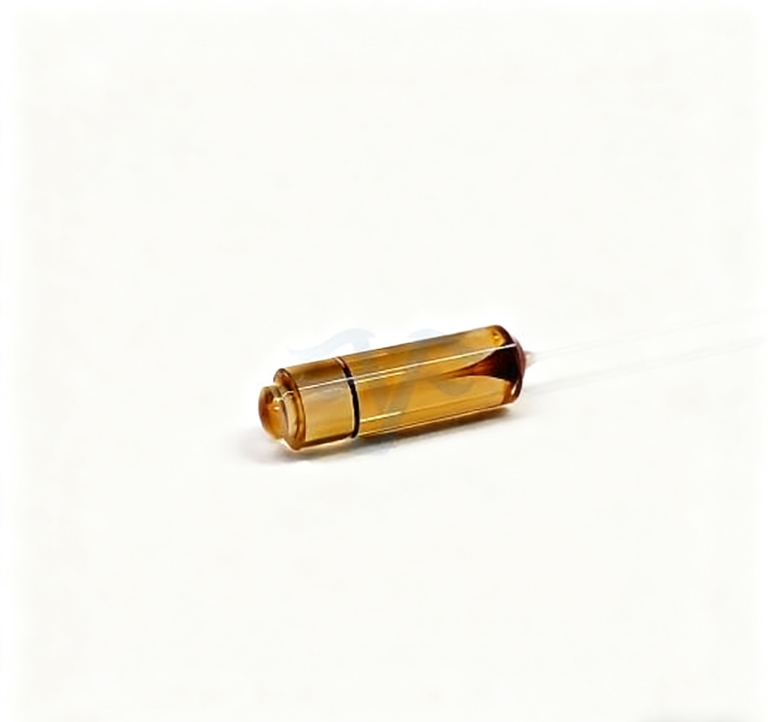
The polarizer packages list 5.5 mm diameter by 35 or 50 mm length, with at least one meter of fiber at each end and separately selectable ordering lengths. Confirm the chosen housing, lead length and connector configuration on the supplied drawing. If the project uses a short embedded lead, its support and axis-identification method should be defined before the source module is assembled.
For a connectorized polarizer, agree protection of the connector face and identification of the two ends during shipment. For a bare-fiber unit, define the exposed lead condition and support so unpacking does not load the small fiber exit. These are product-specific handling requirements to agree with the supplier, not a claim that one universal packing method has been verified for every Feiyi configuration.
At acceptance, measure transmission and rejection for defined states at the selected wavelength. Preserve the launch reference, output analysis and delivered termination. If an SM input is part of the build, control or characterize its launched state instead of treating ordinary continuity as a polarizer test. If a PM output is part of it, verify the orientation that the receiving component actually uses.
For an ideal linear polarizer, the transmitted fraction from a linear input follows the squared cosine of its angle to the passed axis. A 30-degree mismatch would therefore leave 75% before device losses, equivalent to about 1.25 dB of projection loss. This is an idealized illustration, not a Feiyi test result. It explains why an acceptable 0.5 dB component limit does not guarantee that an incorrectly aligned assembly loses only 0.5 dB.
The listed polarizer operating interval is −10 to +75 °C, while its storage interval is −40 to +85 °C. A source module powered during a cold startup needs an operating-condition approval, not just proof that its polarizer survives shipment. If the project requires a defined extinction ratio over that environment, specify the needed measurement condition and obtain confirmation for the chosen wavelength and fiber version.
Keep the optical-state decision visible when ordering spares. A 1310 nm SM-ended polarizer should not be substituted for a 1550 nm PM-ended unit because the housing and lead lengths look the same. Record the band, both fiber ends and selected power version as part of its identity. That lets the maintenance team preserve the source module’s passed state without having to reconstruct the original engineering selection.
Feiyi’s discussion of polarization-maintaining technology provides background for the wider chain. For the inline device, decide the passed axis, fiber construction and usable transmitted power first. If the unresolved issue is a reverse path, take it to the isolator selection; if it is a changing launch state, resolve that source interface before ordering a nominally stronger polarizer.