
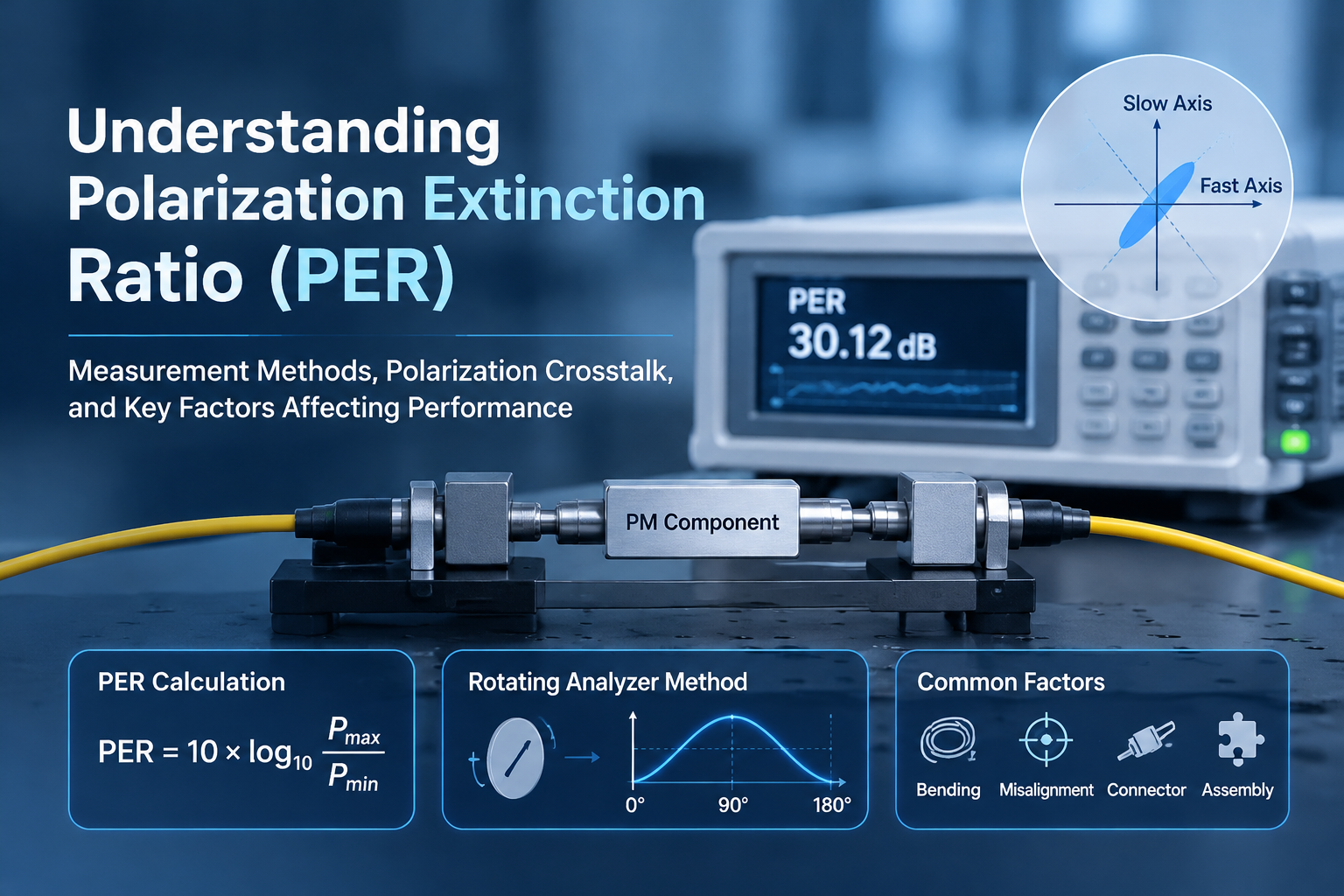
Understanding Polarization Extinction Ratio (PER): Measurement Methods, Polarization Crosstalk, and Key Factors Affecting Performance
Introduction
Polarization Extinction Ratio (PER) is a critical performance parameter for polarization-maintaining (PM) fiber components. It indicates how effectively an optical component preserves the intended polarization state while minimizing unwanted polarization coupling.
For PM couplers, PM patch cords, PM WDM devices, optical isolators, and other polarization-sensitive components, PER plays an important role in determining polarization stability and overall system performance.
However, achieving a high PER involves more than selecting high-quality PM fiber. Fiber-axis alignment, optical assembly accuracy, mechanical stress, connector interfaces, and measurement conditions can all affect the final polarization performance.
How is PER measured in practice? What causes polarization crosstalk? And what factors should engineers consider when evaluating PM optical components?
In this article, we explore the fundamental principles of PER, explain the rotating analyzer measurement method, and discuss common sources of polarization leakage and practical ways to improve polarization performance.
1. What Is Polarization Extinction Ratio (PER)?
Polarization Extinction Ratio (PER) describes the ratio of optical power in the dominant polarization state to the optical power in the orthogonal polarization state.
It is commonly expressed in decibels (dB) and calculated using:
PER (dB) = 10 × log₁₀(Pmax / Pmin)
Where:
- Pmax represents the maximum optical power measured along the dominant polarization direction.
- Pmin represents the minimum optical power measured along the orthogonal polarization direction.
A higher PER indicates better polarization purity and lower unwanted polarization content.
For example:
| PER | Power Ratio |
|---|---|
| 20 dB | 100:1 |
| 25 dB | Approximately 316:1 |
| 30 dB | 1,000:1 |
| 40 dB | 10,000:1 |
Even a small amount of optical power coupled into the orthogonal polarization mode can reduce the measured PER.
For PM fiber components, PER is therefore an important parameter for evaluating polarization-maintaining performance, particularly in applications requiring stable and controlled polarization states.
2. Understanding Polarization Crosstalk in PM Fiber
Polarization crosstalk refers to the unwanted coupling of optical power between two orthogonal polarization modes.
PM fiber is designed with two principal polarization axes, commonly referred to as the fast axis and slow axis. Its high birefringence helps maintain the polarization state of light during propagation by reducing the effects of external disturbances.
Under ideal conditions, light launched along one principal axis remains predominantly in that polarization mode.
In practical systems, however, imperfections in fiber alignment, mechanical conditions, and optical assembly may cause part of the optical power to couple into the orthogonal axis.
This phenomenon is known as polarization crosstalk.
The relationship between polarization crosstalk and PER is closely related: greater unwanted coupling generally results in a lower PER.
Common contributing factors include:
- Incorrect alignment between the input polarization and the PM fiber axis.
- Fiber bending, twisting, or mechanical stress.
- Temperature fluctuations and environmental changes.
- Misalignment during splicing or optical assembly.
- Connector interface and component packaging imperfections.
Understanding these factors is essential when designing, manufacturing, and testing PM optical components.
3. How to Measure PER: The Rotating Analyzer Method
The rotating analyzer method is a practical technique for measuring the polarization extinction ratio of PM fiber components.
Its basic principle is to analyze the output polarization by rotating a linear polarization analyzer and recording the transmitted optical power at different angular positions.
As the analyzer rotates, the detected power changes according to the orientation of its transmission axis relative to the incoming polarization state.
3.1 Typical Measurement Setup
A typical PER measurement system may include:
- Stable laser source: Provides optical power at the specified operating wavelength.
- Input polarization control: A suitable polarizer or polarization adjustment setup is used to align the input polarization with the intended PM fiber axis.
- Device Under Test (DUT): The PM component being evaluated, such as a PM coupler, PM patch cord, or PM optical assembly.
- Rotating analyzer: Measures the output polarization by analyzing different polarization orientations.
- Optical power meter or detector: Records the transmitted optical power during analyzer rotation.
The measurement configuration should be selected according to the component type, operating wavelength, and applicable testing requirements.
3.2 Measurement Procedure
Step 1: Prepare the optical source
Select a stable light source operating at the required wavelength.
Allow the source to stabilize before measurement. Ensure that the optical power is appropriate for the detector and measurement system.
Step 2: Align the input polarization
Adjust the input polarization to match the intended principal axis of the PM fiber.
Accurate alignment is important because an incorrectly launched polarization state may introduce additional orthogonal polarization content before the light even enters the device under test.
Step 3: Connect the device under test
Connect the PM component to the measurement setup.
Check the fiber-axis orientation and connector alignment. Avoid excessive bending, twisting, pulling, or mechanical pressure on the fiber.
Step 4: Rotate the analyzer
Rotate the analyzer through 180° while recording the transmitted optical power at different angular positions.
The analyzer should cover the full measurement range with sufficient angular resolution to identify the maximum and minimum power levels.
Step 5: Identify the maximum and minimum power
From the recorded measurement data, determine:
- Pmax: Maximum transmitted optical power.
- Pmin: Minimum transmitted optical power.
The maximum and minimum correspond to the analyzer orientations with the strongest and weakest transmission, respectively.
Step 6: Calculate PER
Apply the following formula:
PER (dB) = 10 × log₁₀(Pmax / Pmin)
For example, if the measured maximum power is -5 dBm and the minimum power is -35 dBm:
PER = -5 dBm – (-35 dBm) = 30 dB
The measured PER is therefore 30 dB.
3.3 Important Measurement Considerations
Reliable PER measurement requires careful control of the test environment and measurement equipment.
Engineers should pay particular attention to:
- Light source stability: Fluctuating input power can affect measurement consistency.
- Polarization alignment: Incorrect launch conditions may lead to misleading results.
- Fiber handling: Bending, twisting, and mechanical stress should be minimized.
- Analyzer performance: The analyzer should have sufficient extinction capability for the expected PER range.
- Detector sensitivity: The measurement system must be able to accurately detect low optical power levels.
- Background noise: Stray light, detector noise, and instrument limitations can affect the measured minimum power.
- Measurement repeatability: Repeated measurements under consistent conditions help verify result stability.
It is also important to consider the measurement system’s own extinction ratio. When the DUT has a high PER, the analyzer and detector limitations may become the dominant factors affecting the measured result.
For this reason, instrument calibration and the applicable component test specifications should always be considered when reporting PER.
4. Common Factors That Reduce PER
Even PM fiber components manufactured with high-quality materials can experience polarization leakage.
The following factors are particularly important during optical component manufacturing and assembly.
4.1 PM Fiber Axis Misalignment
PM fiber contains two principal polarization axes. If the input polarization is not accurately aligned with the intended axis, a portion of the optical power may propagate in the orthogonal polarization mode.
This is especially important during:
- PM fiber splicing.
- PM connector termination.
- PM collimator alignment.
- PM coupler assembly.
- Integration of multiple PM optical components.
Accurate axis identification and alignment are essential for maintaining high PER.
4.2 Mechanical Stress and Fiber Bending
PM fiber performance can be affected by external mechanical conditions.
Excessive bending, twisting, compression, or tension may introduce additional birefringence and polarization coupling, depending on the fiber design and stress conditions.
During assembly and installation, appropriate fiber routing and mechanical protection can help reduce these effects.
4.3 Connector and Optical Interface Conditions
PM connectors require careful attention to polarization-axis orientation.
Improper key alignment, inconsistent connector orientation, contamination, and poor end-face quality may affect the repeatability and performance of PM optical connections.
For PM patch cords and fiber assemblies, maintaining consistent axis orientation across the optical interface is particularly important.
4.4 Optical Assembly and Packaging Accuracy
The final PER of a PM optical component depends not only on the fiber itself but also on the complete assembly process.
For example, during the manufacturing of PM couplers, collimators, and other optical devices, small alignment deviations or mechanical stress introduced during bonding and packaging may affect polarization performance.
Consistent assembly procedures, accurate optical alignment, and controlled packaging processes help improve product repeatability.
4.5 Intrinsic Fiber and Component Characteristics
The intrinsic properties of PM fiber and the internal optical structure of a component can also influence polarization performance.
Fiber birefringence, manufacturing tolerances, optical coatings, internal optical interfaces, and component design all contribute to the final result.
Therefore, the PER specification of the fiber alone should not be treated as the guaranteed PER of a completed optical component.
The entire optical assembly must be evaluated under appropriate measurement conditions.
5. Practical Ways to Improve PER Performance
Improving PER requires coordinated control of optical design, component manufacturing, assembly, and testing.
The following practices can help achieve more consistent polarization performance:
1. Select suitable PM fiber
Choose PM fiber with appropriate operating wavelength, polarization characteristics, and mechanical properties for the intended application.
2. Improve polarization-axis alignment
Use appropriate axis-identification and alignment techniques during splicing, connectorization, and optical assembly.
3. Minimize mechanical stress
Control fiber bending radius, twisting, tension, and pressure during manufacturing and installation.
4. Optimize assembly and packaging processes
Maintain consistent alignment, bonding, fixation, and fiber-routing procedures to minimize unwanted stress.
5. Control connector orientation
Ensure that PM connector keys and polarization axes are correctly aligned throughout the optical path.
6. Establish reliable PER testing procedures
Use suitable measurement instruments, controlled input conditions, and repeatable testing methods to evaluate the completed component.
For high-performance PM devices, PER should be tested at the finished component level rather than estimated solely from the PM fiber datasheet.
6. Why Is PER Important in PM Optical Applications?
PER is an important parameter in applications where polarization stability affects optical signal quality, measurement accuracy, or system performance.
Fiber Optic Sensing
PM components can help maintain a controlled polarization state in precision fiber sensing systems, supporting consistent optical measurements.
Fiber Lasers and Optical Amplifiers
PM couplers, isolators, WDM devices, and other polarization-sensitive components are used in fiber laser and amplifier architectures where polarization stability may be important.
Optical Communication Systems
Certain optical communication and signal-processing systems require polarization-maintaining components to support stable optical operation.
Scientific Research and Precision Measurement
In laboratory instruments and advanced optical systems, controlled polarization states are essential for repeatable experiments and accurate measurements.
The required PER varies depending on the application, system architecture, and component specifications. Engineers should therefore select PM components according to the actual requirements of their optical systems.
Conclusion
Polarization Extinction Ratio (PER) is a key performance parameter for evaluating the polarization-maintaining capability of PM fiber components.
The rotating analyzer method provides a practical way to measure PER by analyzing the maximum and minimum transmitted optical power at different analyzer orientations.
However, the final PER is influenced by many factors, including fiber-axis alignment, polarization crosstalk, mechanical stress, connector conditions, optical assembly accuracy, and measurement system limitations.
For optical component manufacturers, controlling these factors throughout the design, assembly, and testing processes is essential for achieving reliable and repeatable polarization performance.
At Feiyi Optoelectronic, we manufacture PM fiber components and customized passive optical assemblies for optical communication, fiber sensing, and other polarization-sensitive applications.
Our product range includes PM patch cords, PM couplers, PM WDM devices, and other customized PM optical components.
For technical inquiries or customized component requirements, please visit https://www.feiyi-oeo.com/ or contact our team.
Feiyi Optoelectronic – Passive Optical Components Manufacturer | OEM & ODM Solutions
