A PM Fiber Patch Cord Supplier Should Resolve Axis Alignment Before the Cable Length
The jumper fits both sockets and the power meter shows light, yet the polarization measurement is wrong. That is a familiar type of integration problem when a cable order defines wavelength and connector shape but leaves the PM axis ambiguous. A PM fiber patch cord supplier should help an instrument OEM or laboratory agree the polarization reference at both cable ends before the order becomes a list of lengths. Feiyi’s custom PM fiber patch cords list axis, jacket and connector choices; its separate 1550 nm PM patch cord provides a wavelength-specific starting point.
Write two end definitions, not one connector label. Identify the connector and polish at End A and End B, the fiber’s working axis relative to each key, and the wavelength at which the assembly must preserve the required polarization.
Give the PM fiber patch cord supplier an End A and End B axis drawing
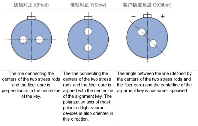
Start from the two devices the cable will connect. The source may define its preferred polarization relative to an FC connector key, while the receiving component may specify slow-axis operation. A cable ordered as “PM, FC/APC, 1 m” leaves the relationship between those references unstated. Put each interface on a drawing and state whether the intended connection preserves the same axis or implements a deliberately different orientation.
Feiyi’s custom PM patch-cord ordering information lists slow-axis and fast-axis alignment choices. This is a useful ordering field precisely because the cable is an optical orientation assembly, not just a piece of fiber with two plugs. Choose the field to suit the connected devices. A slow-axis convention is not something to assume from a photograph of a green connector.
FC/APC connector polish does not define the PM fiber’s slow axis
The connector polish describes the optical contact geometry; the PM-axis reference describes the fiber orientation. Keep the two requirements separate on the order. An FC/APC cable with the wrong orientation can still appear mechanically compatible, while a correctly oriented PM fiber with the wrong polish may not suit the intended mating interface. The end-to-end definition should state both requirements explicitly.
OZ Optics’ PM patchcord and connector documentation explains the key-to-axis relationship used for repeatable PM connections. For a Feiyi order, use that relationship to frame the drawing, then confirm the supplier’s actual end convention. The background document is not evidence of the tolerance delivered on a different manufacturer’s jumper.
PM jumper adapters must preserve the agreed connector-key reference
The adapter between two connectors is part of the orientation system. Specify the compatible key and mating arrangement instead of selecting an adapter only because the two ferrules can touch. A connection with rotational freedom may give different results after reconnection. That is particularly troublesome when an OEM wants a field-replaceable cable to reproduce a factory-approved optical path.
Thorlabs’ PM patch-cable guidance discusses key and slot compatibility. Apply that general interface lesson to the adapter choice, but obtain the actual dimensions and orientation agreement for the Feiyi assembly. The purchase record should identify the approved mating hardware rather than leaving it as an unnamed bench accessory.
Select the PM patch-cord wavelength before copying a previous cable order
Feiyi lists separate PM patch cords at 780 nm, 1064 nm, 1310 nm and 1550 nm, among other wavelengths. These choices should follow the optical route, not the jacket color. The 1550 nm listing identifies PM1550 fiber; the 1310 nm patch cord identifies PM1310; and the 1064 nm patch cord identifies PM1060. Record that designation with the wavelength in the approved specification.
For a laboratory moving from one source wavelength to another, an old cable can look like an economical reuse option. The appropriate question is whether its fiber and performance specification fit the new wavelength and connected devices. Ask the engineer to identify the new source band and required polarization behavior, then compare the relevant Feiyi variant. Avoid accepting a different wavelength product simply because the connector type and physical length match the previous order.
A 780 nm PM jumper belongs in a different wavelength evaluation from a 1550 nm jumper
The PM 780 nm optical patch cord identifies PM780 fiber. If a test station uses both 780 nm and 1550 nm sources, keep the approved cable types individually identifiable. A shared connector style makes accidental substitution easier, so the receiving and storage description should include wavelength and fiber designation. It should not rely only on length or a vendor’s internal order number.
The wavelength-specific Feiyi listings also describe configurable fast-axis, slow-axis or custom orientation. That means a wavelength match is necessary but does not finish selection. The supplier must confirm the orientation convention for the purchased configuration, especially when the cable connects to an axis-selective component. One accepted source wavelength does not erase the need for the two-end drawing.
AFW Technologies’ PM patchcord information provides external background on aligned and special-orientation assemblies. The general distinction is useful when discussing a customized interface. Any special alignment, tolerance or construction for the Feiyi cable still needs to be agreed for that cable rather than inferred from another supplier’s examples.
Cable jacket and lead length should follow the instrument’s actual PM-fiber route
Feiyi’s custom patch-cord ordering information lists 250 µm, 900 µm, 2 mm and 3 mm construction choices, along with example lengths of 0.5 m, 1 m, 2 m and 3 m. Those fields let the optical team describe the assembly’s physical route. A compact internal instrument lead and a detachable bench cable need different mechanical consideration even when both connect the same two wavelengths.
For an OEM converting a prototype into a serviceable instrument, begin with the enclosure route and the connector-access points. A long bench cable may leave an unnecessary loop inside the production enclosure; a short production cable may pull against the connector when the lid opens. Define the required length from the intended installation and confirm how the supplier measures it. Do not turn an example length in an ordering table into an assumed delivered default.
A connectorized PM patch cord and a PM pigtail support different assembly processes
If the instrument requires a permanently integrated fiber end rather than two removable connections, compare the construction with Feiyi’s custom PM single-fiber pigtail offering. A pigtail can be relevant to an assembly process that terminates or splices one end internally. It does not perform the same service role as a complete detachable jumper between two external ports.
That distinction affects which end is exposed during handling and what information must accompany the part. A two-ended patch cord needs two connector definitions and an end-to-end orientation requirement. An integrated pigtail needs a clear account of the open end and the downstream assembly operation. Agree the construction with the engineer before the purchaser consolidates both under the word “cable.”
For delivery, request protection appropriate to the selected construction. Connectorized PM jumpers should arrive with the optical ends protected and each cable identifiable by its approved wavelength and orientation configuration. If several lengths share one outer shipment, individual identification should prevent the assembly team from opening every cable to determine which one it is. Agree how the cable will be coiled and restrained so the chosen jacket is not crushed; the published options do not establish a particular standard carton or coil diameter.
Measure PM-jumper extinction ratio after the same connection sequence the instrument will use
Total transmitted power answers only part of the acceptance question. A PM cable also needs a measurement that shows the intended polarization is preserved under the agreed launch and connection conditions. Feiyi’s wavelength-specific 1550 nm listing gives a minimum extinction ratio of 22 dB. Confirm the applicable test arrangement and acceptance limit for the exact purchased assembly rather than treating an unqualified number as a complete test method.
A useful bench sequence starts with a known source orientation and a stable reference connection. Measure the optical result, insert the cable with the approved adapter arrangement, and then evaluate the desired polarization at its far end. Keep the source and reference setup unchanged while reconnecting the cable. That lets a change in the measurement be investigated at the connection rather than being confused with a source adjustment.
Remating a PM connector should not introduce an undocumented axis change
Repeat the connection sequence that the instrument or service procedure will require. If a cable is intended for routine replacement, a result recorded only before the first disconnection is incomplete evidence for that use. Record the observed behavior after reconnecting the approved hardware and identify which end was remated. Avoid swapping the adapter, cable and source alignment simultaneously, because the result would not identify the cause of a change.
SQS’s PM patch-cord information identifies active PM-fiber alignment as a key part of connector assembly. The implication for acceptance is to verify the delivered assembly as an orientation-sensitive component. Neither its appearance nor a basic continuity check establishes the PM behavior required by the instrument.
Separate the cable’s declared limit from the test system’s own capability. If the reference jumper or source launch already produces poor extinction, a reading at the delivered cable’s output will not isolate the cable’s contribution. Agree the reference arrangement, measurement wavelength and handling sequence with the optical team before evaluating a supplier lot. This is a proposed project test, not a claim that Feiyi provides a particular instrument-level acceptance report as standard.
Keep the approved PM cable-end definition attached to the repeat order
A practical handoff to purchasing can be short while remaining precise: operating wavelength and fiber designation; End A connector and key-to-axis convention; End B connector and convention; selected jacket; measured cable length; and the agreed optical acceptance conditions. Add the drawing revision and identify the mating adapter used during sample approval. This record is more useful than a description containing only “high-quality PM fiber patch cord.”
The same record should make substitutions visible. If a later instrument version changes from a 1550 nm source to a 1310 nm source, the corresponding Feiyi wavelength variant should be reviewed. If service access changes the required length, confirm that change against the cable route. If a connected component requires a different axis convention, update the end definition rather than expecting the old cable part number to describe the new interface.
Feiyi’s comparison of PM and standard patch cords is useful when the team is deciding whether polarization preservation is actually required. For a PM design already approved, keep that requirement intact through the order, incoming identification and bench connection. A low-loss ordinary jumper is not an axis-preserving substitute just because it connects the same sockets.
Send the supplier the two-end drawing before the length schedule. Once the sample reproduces the intended polarization through the specified adapters, attach its configuration to the order and keep the same definition for replacement cables. The engineer, buyer and receiving technician should be able to point to the same axis convention without having to reconstruct it from the original laboratory setup.