Define Two Different Maps in a PM MPO Patch Cord Supplier Request
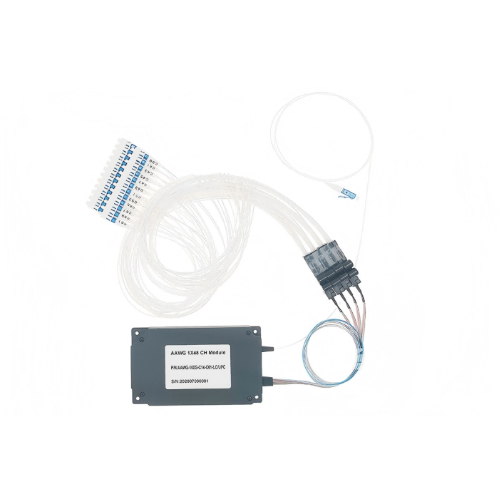
A multi-channel instrument can have perfect fiber continuity and still send the wrong polarization to every receiver. That happens when connector position and PM-axis orientation are treated as one requirement. A PM MPO patch cord supplier request needs two independent maps: which fiber connects to which position, and which polarization axis each connection preserves. Feiyi’s MPO/MTP assemblies provide a mechanical connectivity reference, while its custom PM patch cords provide documented polarization-oriented choices. Confirm a PM MPO build specifically; standard single-mode MPO figures do not establish its PM performance.
For an OEM measurement system, the first deliverable should be a channel drawing with orientation references at both connector ends. A generic instruction for “PM MPO, low loss” leaves fiber type, fiber count, endpoint geometry and per-channel acceptance open. Treat the requested combination as an engineering configuration to agree, rather than assuming that two compatible-sounding family names define a supplied assembly.
A PM MPO patch cord supplier needs a position map before a polarization map
Imagine an instrument with several optical sources and several polarization-sensitive receivers in one compact connector interface. Position 1 at the source end may need to reach a particular receiver position at the other end. Define that route for every populated fiber and show both connector viewing directions. Connector polarity describes channel routing; it does not by itself describe the orientation of a PM fiber’s fast or slow axis.
Feiyi’s standard MPO/MTP entry distinguishes male and female housing assemblies and several housing formats. Round connector kits are listed at 60.2 mm length; oval kits at 45.6 mm; bare-ribbon kits at 43.0 mm. These dimensions concern offered mechanical forms, not a universal PM MPO specification. Select the intended mating interface and request confirmation that the proposed PM configuration uses the required envelope.
MPO pin gender and key orientation are mechanical requirements
Pin gender must agree with the mating interface. A fiber map also needs the connector’s key orientation and viewing reference. If one drawing is read from the ferrule face and another from the cable side, the same printed position sequence can be interpreted differently. Include a visual end reference so the instrument team, cable assembler and receiving engineer use the same map.
US Conec’s MTP connector information describes its branded MPO-compatible connector family. Its MTP PRO documentation illustrates that polarity and pin configuration are connector-system choices. Those capabilities should not be assumed for every Feiyi or generic MPO assembly. Specify the actual supplied connector construction when the project depends on such a feature.
PM multi-fiber axis approval is separate from MPO continuity
Once the position map is defined, assign a polarization reference to each populated PM fiber. State whether the required transmitted reference is fast or slow axis and how it relates to the ferrule or connector key. Specify the orientation at both ends; a list of channel numbers alone does not establish that the receivers see the intended states.
Feiyi’s custom PM patch-cord ordering information includes slow- or fast-axis alignment, wavelength options of 780, 850, 980, 1064, 1310 and 1550 nm, and different lead constructions. These are useful fields for the PM portion of a request. They do not prove that the same choices are available in every MPO ferrule format. Ask the manufacturer to confirm the complete combination, including channel population and axis relationship, before approving an assembly.
Per-channel PM1550 orientation cannot be inferred from an MPO label
A purchaser may receive a standard SM MPO loss table and mistakenly treat “single mode” as equivalent to “polarization maintaining.” It is not. A single-mode channel designation does not define an axis-preservation requirement. For a 1550 nm PM instrument, identify the selected PM fiber and its per-channel polarization acceptance, with the launch and output analysis reference stated. The standard MPO table remains relevant to mechanical and ordinary connector choices only within its actual scope.
The custom PM lead description notes that connectors can change the applicable insertion-loss, return-loss and extinction-ratio allowances relative to unconnectorized conditions. For a requested multi-fiber connector, agree the measured endpoints explicitly. Do not apply a bare-fiber PM value to a delivered MPO assembly without confirmation, and do not use an ordinary MPO transmission result as evidence that a channel maintains the selected axis.
The two drawings should answer different questions. The position drawing answers “where does this fiber go?” The axis drawing answers “what polarization reference reaches that destination?” A correct answer to one does not establish a correct answer to the other.
PM pigtail arrays offer another interface when the instrument does not need MPO mating
Feiyi’s four-fiber PM pigtail and sixteen-fiber PM pigtail are separate multi-fiber product options. They should not be described as MPO patch cords. They may be relevant when the OEM integrates fibers into an embedded optical assembly instead of requiring a detachable standardized multi-fiber connector.
The four-fiber entry lists a minimum extinction ratio of 18 dB, while the sixteen-fiber entry lists 16 dB. Both list wavelength choices including 630, 780, 850, 980, 1064, 1310 and 1550 nm, with corresponding PM fiber families. Those values describe those pigtail products. They cannot be transferred to a custom PM MPO build simply because it also contains several fibers.
A sixteen-fiber pigtail is not evidence for a sixteen-channel MPO configuration
A package team may need sixteen internal optical connections and choose a pigtail arrangement that fits its assembly. A field-replaceable instrument may instead need a detachable MPO interface with a particular populated ferrule geometry. The two buyers have different mechanical boundaries. Confirm whether the design needs embedded optical ends, detachable connector mating or a breakout between the two before selecting a fiber count.
SQS’s fiber-array documentation provides background on embedded multi-fiber optical interfaces. Its array geometry is not a specification for Feiyi’s pigtails or for an MPO connector. Use it to understand why pitch, alignment and mechanical support belong to an array request, then define the actual selected interface independently.

Separate PM MPO acceptance into continuity, connector loss and polarization
Continuity testing verifies the position map. Connector-loss testing evaluates the delivered optical connections under the selected wavelength and reference conditions. Polarization testing evaluates each PM channel’s preserved reference and unwanted orthogonal contribution. A single overall “passed” entry obscures which property was measured. Request channel identities and conditions that let the receiving team interpret each result.
The standard Feiyi MPO table lists standard and low-loss ferrules, with typical single-mode loss entries of 0.50 and 0.30 dB respectively. It also distinguishes PC and APC finishes. These figures can help define a question about the proposed termination, but they should not be asserted as the guaranteed loss of an unconfirmed PM MPO configuration. Obtain the selected build’s own applicable limits and connector inclusion conditions.
A passing fiber-position map can still conceal a rotated PM channel
If the instrument launches the intended state on channel three and sees continuity at the correct destination, the position map passes. If that channel’s axis arrives rotated relative to the receiver, the polarization requirement can still fail. Record both outcomes separately. This makes a discrepancy useful to the manufacturer: it identifies whether the problem concerns routing, the endpoint axis or the optical measurement arrangement.
OZ Optics’ PM connector guidance explains axis alignment as a separate interface property. For the proposed Feiyi multi-fiber assembly, apply that principle per channel with the actual ferrule reference. Do not claim a uniform per-channel extinction ratio from a successful ordinary patch-cord measurement on one different connector format.
Use a controlled input state when testing polarization. An uncontrolled source can make channel comparisons difficult to interpret. Preserve the wavelength, launch condition, analyzed output and connector mating arrangement for each required channel. This is a proposed acceptance definition, not a report that Feiyi has already performed a particular test on the requested custom assembly.
If the instrument uses different wavelengths on different channels, identify them individually rather than assigning a broad band to the whole connector. The custom PM lead and multi-fiber pigtail options list several distinct fiber families. A channel intended for 780 nm and one intended for 1550 nm need their appropriate confirmed fibers and optical conditions. A common ferrule joins their mechanical interfaces; it does not make their wavelength-specific fiber choices interchangeable.
When a sample has breakout leads, preserve the relationship between each breakout identifier and its MPO position before checking its axis. A receiver label added after the fibers are installed is not a reliable substitute for that original mapping. A useful sample record follows the same populated fiber through position, breakout end, launched state and analyzed output. That makes an incorrect axis distinguishable from a mislabeled destination without assuming that every observed error requires rebuilding the connector.
The PM multi-fiber pigtail entries list maximum optical power of 500 mW, but that figure belongs to the selected pigtail construction. For an MPO request, describe the intended power at each populated channel and obtain approval for its own termination. Do not add several channel ratings to create an assumed ferrule-wide rating, or use a separate pigtail’s number to authorize the PM connector assembly. Per-channel optical identity and complete mechanical construction need to be reviewed together.
Release a PM MPO request only after its complete configuration is confirmed
Ask for a drawing that joins the requested ferrule population, pin gender, key orientation, fiber type, axis map, cable construction and end identification. Feiyi’s custom PM lead options include 250 µm, 900 µm, 2 mm and 3 mm constructions, but the selected multi-fiber cable arrangement needs its own approval. A loose-tube single-fiber ordering choice should not be treated as the established cable construction for an MPO trunk.
For a detachable assembly, agree protection of the multi-fiber endfaces and identification that survives unpacking. For a breakout, identify the individual ends so the receiver map remains usable after routing. If the alternative is an embedded pigtail, protect the optical ends and support the assembly without loading the exposed fibers. Confirm these requirements for the selected build rather than describing an undocumented standard shipping package.
The four- and sixteen-fiber pigtail entries list an operating interval of +10 to +60 °C. The standard MPO entry lists −20 to +60 °C. These are different products with different stated conditions. A requested PM MPO assembly needs an approved operating interval for its own configuration; selecting the broader interval from the ordinary connector table would not establish the PM assembly’s environmental acceptance.
Feiyi’s article on PM fiber patch cords in polarization-sensitive systems is useful background for the single-channel reference. Carry that discipline into every populated channel of the proposed multi-fiber interface, while keeping connector position and axis orientation as separate approvals.
Send the two maps with the sample request and ask which complete configuration can be supplied. If an axis or ferrule arrangement remains unconfirmed, keep it open rather than borrowing the standard MPO limits. The order becomes ready when the actual delivered interface, per-channel measurements and instrument destinations all describe the same build.