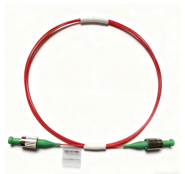
PM Fiber Patch Cord Manufacturer: Turn a Prototype Cable Into a Repeatable Build
A buyer evaluating a PM fiber patch cord manufacturer is often not buying a cable for the first time; the harder job is turning a successful prototype cable into a repeatable production item. A patch cord that looks correct can still be wrong for the optical system if its wavelength family, connector polish, polarization axis, fiber construction, or lead length does not match the approved build. Feiyi’s PM patch-cord range covers 780, 850, 980, 1064, 1310, and 1550 nm on the main product table, with separate product pages extending the family from 630 to 1550 nm.
For OEM instruments, fiber lasers, amplifiers, and test equipment, the first purchasing question should therefore be: which parts of the prototype must be frozen so the next batch behaves the same? Feiyi’s published ordering structure separates operating wavelength, grade, axis alignment, pigtail type, connector type, and fiber length. That structure is more useful for a repeat order than a description such as “1 m PM FC/APC cable,” because it records the optical decisions that make the assembly polarization-maintaining.
A PM fiber patch cord manufacturer needs the approved optical build, not only the cable length
Cable length is visible and easy to specify, but it is rarely the first optical variable. A production handoff should identify wavelength, PM fiber family, connector polish, grade, axis orientation, jacket or pigtail construction, and the exact end-to-end length. If one of those items changes, the replacement may remain physically compatible while no longer matching the performance measured during prototype approval.
Wavelength-specific PM fiber should stay tied to the part number
Feiyi’s main PM patch-cord specification lists operating wavelengths of 780, 850, 980, 1064, 1310, and 1550 nm and fiber types PM780, PM850, PM980, PM1310, and PM1550. The product range also includes individual pages such as PM 980 nm Optical Patch Cord, PM 1064 nm Optical Patch Cord, PM 1310 nm Optical Patch Cord, and PM 1550 nm Optical Patch Cord.
An engineering team supporting both 1064 nm and 1550 nm instruments should not use one generic drawing simply because the connector shell and cable diameter are similar. Keeping wavelength and approved PM fiber on the controlled part record makes substitution visible before installation.
APC and UPC grades carry different published loss and return-loss limits
Feiyi’s product table separates APC and UPC versions and two grades. For insertion loss, the published limits are ≤0.40 dB and ≤0.50 dB for the two APC grades, and ≤0.30 dB and ≤0.40 dB for the two UPC grades. Return-loss limits are ≥60 dB and ≥50 dB for APC, and ≥55 dB and ≥50 dB for UPC. The table lists extinction ratio of at least 20 dB across the configurations.
Those figures show why connector polish is not merely a mechanical preference. A buyer should choose APC or UPC to match the mating interface and the optical-reflection requirements of the instrument, then use the corresponding acceptance values. Copying an APC return-loss target onto a UPC drawing, or vice versa, would create an unnecessary receiving dispute.
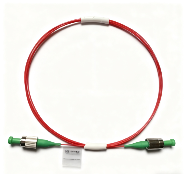
PM fiber patch cord manufacturer qualification should include repeatability and interchangeability
A one-off prototype can be adjusted until it works. A production cable has to mate with multiple instruments and replacement parts without requiring a technician to rediscover the alignment each time. Feiyi publishes repeatability of ≤0.1 dB and interchangeability of ≤0.2 dB on the PM patch-cord page, together with plug-cycle life of at least 1000 times and durability of ≤0.2 dB.
Those specifications are useful for buyers who expect cables to be disconnected during calibration, maintenance, or service. They also give distributors and OEMs a reason to treat a PM patch cord as an optical component rather than as a generic accessory.
A test-instrument manufacturer needs replacement cables that do not reset the optical baseline
Feiyi lists test instruments among the applications for its PM patch cords. In a measurement system, replacing a damaged cable should not force the operator to accept a large unexplained optical shift. The approved cable record should therefore preserve the connector grade, wavelength family, axis convention, and length used when the instrument baseline was established.
Incoming inspection can compare insertion loss and extinction ratio under a defined launch condition, while the instrument manufacturer can separately record its own system baseline. This separates cable acceptance from the complete instrument calibration and makes fault finding more disciplined.
A fiber-laser assembly may care about connector reflection and axis orientation at the same time
Feiyi also lists fiber lasers and fiber amplifiers as applications. In those systems, a patch cord can sit next to a PM isolator, circulator, coupler, or VOA. Connector reflection, loss, and polarization orientation can therefore affect different parts of the chain at once. The cable cannot be selected from connector type alone.
If the laser platform is already standardized on an APC interface, procurement should maintain that interface through the approved patch cord. If the PM device on the other end uses a defined connector-key orientation, the cable drawing should carry the same axis convention so the installer does not have to infer it.
The connector key must agree with the PM fiber axis in a repeatable build
Feiyi’s PM patch-cord page states that for devices with connectors, the key is aligned to the slow axis. The ordering table also exposes slow-axis and fast-axis alignment as selectable fields. That distinction should be captured explicitly when the customer’s system uses a non-default orientation.
Do not use a color label as the only axis-control method
Color can help technicians identify cable families, but it is not a geometric datum. The controlled drawing or part description should state the required axis alignment relative to the connector key. That instruction remains meaningful even if boot colors, labels, or cable jackets change during a later build.
This is particularly important for service spares. A replacement cable may be stored for months before installation. The person fitting it should be able to determine the correct optical orientation from the approved part definition rather than from tribal knowledge about how an earlier batch looked.
Connectorized performance should use connectorized acceptance values
The Feiyi page notes that its base specifications are without connectors and states that for connectorized devices insertion loss is 0.3 dB higher, return loss is 5 dB lower, and extinction ratio is 2 dB lower. A buyer should apply the correct set of limits to the configuration actually ordered.
This prevents a common paperwork problem: the prototype was measured as a finished connectorized cable, but the procurement sheet later copies values from a bare-fiber table. If the acceptance document follows the final assembly instead, receiving inspection and supplier testing are working from the same definition.
Manufacturing handoff should preserve pigtail construction as well as optical performance
Feiyi’s ordering table lists pigtail-type choices including 250 µm, 900 µm, 2 mm, and 3 mm formats. It also lists FC, SC, and LC connector options with UPC/APC variants, and fiber-length codes including 0.5 m, 1.0 m, 2.0 m, and 3.0 m. Those construction choices affect routing, strain relief, panel access, and how the cable is handled during assembly.
For an OEM enclosure, the useful cable drawing should show where the patch cord bends, whether the lead passes through a gland or cable guide, and how much service loop is needed. The supplier does not need the complete confidential instrument design, but the buyer does need to choose a pigtail construction that fits the physical job.
A compact photonics module and a laboratory rack should not share the same cable assumption
A compact optical module may need a short lead with minimal excess cable and a pigtail format that can be routed inside a constrained housing. A laboratory rack may benefit from a more protected cable construction and additional reach between instruments. Both can use the same wavelength and connector polish while needing different mechanical builds.
That is why length should be measured from the installed routing path rather than guessed from the straight-line distance between ports. The final dimension should include the path around bends and service access while respecting the project’s own bend-radius rules.
For a PM fiber patch cord manufacturer, sample approval should become a controlled build record
After a sample passes, record the exact Feiyi product family or ordering description, operating wavelength, grade, axis alignment, pigtail type, connector type at each end, fiber length, and the optical limits used for acceptance. Photographing the sample can help receiving staff, but the photograph should supplement rather than replace the technical record.
The Custom Polarization-Maintaining PM Fiber Patch Cord page is the most useful place to review the complete ordering structure. The PM Fiber Patch Cord range provides wavelength-specific product navigation. Feiyi’s earlier article A PM Fiber Patch Cord Supplier Should Resolve Axis Alignment Before the Cable Length focuses specifically on axis alignment; the manufacturing handoff described here is broader and is intended to keep the approved cable build stable across repeated orders.
A distributor can use the same logic for inventory. Separate stock by wavelength and connector polish first, then preserve axis alignment and cable construction in the SKU description. Two cables that share FC/APC connectors should not be merged into one bin if one is a 980 nm PM build and the other is a 1550 nm build.
PM patch-cord receiving checks should begin at the connector end face
Connector contamination can create loss or reflection that is wrongly blamed on the PM fiber or axis alignment. For connectorized assemblies, receiving and service procedures should therefore begin with the same practical sequence used for other precision fiber links: identify the correct cable, inspect the connector end face with appropriate fiber-inspection equipment, clean it when required, and only then perform optical measurements. This does not replace the manufacturer’s own production test; it prevents dirt introduced during handling from distorting the buyer’s acceptance result.
Shipping protection should preserve the approved connector and bend condition
Feiyi’s public PM patch-cord page specifies optical and construction options but does not publish one universal shipping package for every customized cable. Buyers with sensitive service or production workflows should agree on the delivery condition for the exact assembly: connector dust protection, cable identification, and a coil or routing condition that does not place unnecessary stress on the fiber. These requirements are especially useful when multiple wavelength variants arrive in the same shipment.
For repeated OEM deliveries, the receiving label can carry the customer part number together with the approved Feiyi configuration or wavelength. That simple control helps prevent a 980 nm and 1064 nm cable from being confused because their jackets and connectors appear similar. Packaging then serves the engineering record instead of becoming a separate, undocumented convention.
Release the order only when another technician could reproduce the same cable
A strong PM patch-cord purchase description is not long, but it is unambiguous. It names the wavelength family, PM fiber, grade, connector polish, axis-to-key convention, pigtail construction, and length. It also identifies which published or project-specific optical limits will be checked after manufacturing.
If a future buyer can read that record and order the same configuration without opening the original instrument or asking the engineer what “the blue PM cable” meant, the handoff has done its job. That repeatability is the practical value of working with a PM fiber patch cord manufacturer rather than treating a polarization-sensitive assembly as a commodity cable.