PM WDM Manufacturer: Choose Filter WDM or DWDM Before the Port Drawing Is Released
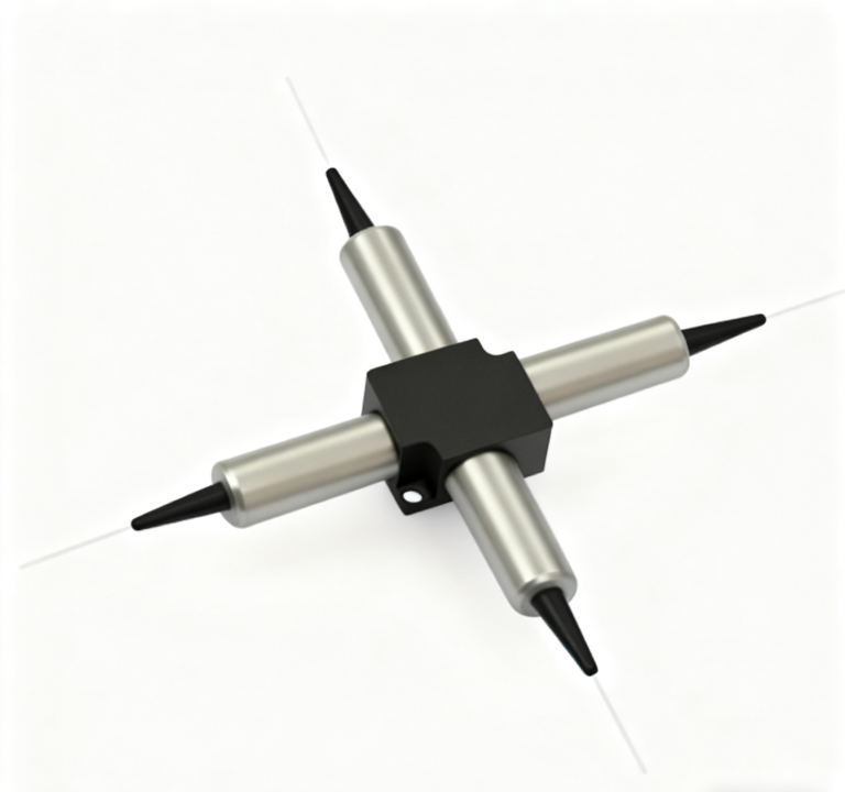
A buyer looking for a PM WDM manufacturer should decide what kind of wavelength-separation job the instrument needs before freezing a three-port drawing. Feiyi’s current PM range includes a Polarization Maintaining Filter WDM and wavelength-specific PM DWDM 3-port products at 1064, 1550, and 2000 nm, plus a PM 100G/200G DWDM 3-port device. Those products may share a compact fiber-component form factor, but they belong to different wavelength plans and should not be treated as interchangeable parts.
For an engineer, the first useful document is a wavelength-and-port map: which wavelength enters the common port, which wavelength should pass, which wavelength should reflect or route to the other port, what PM fiber and axis convention surround the device, and how much insertion loss the system can accept. Once that optical job is clear, the manufacturer conversation can move to package, connector, and lead length. Starting with a generic “3-port PM WDM” request reverses that order and makes later revisions more likely.
A PM WDM manufacturer should receive the wavelength plan before the port labels
A three-port component is easy to draw as three lines around a box. The difficult part is defining what each line means spectrally. Feiyi’s PM Filter WDM page publishes several channel and reflection wavelength combinations, including channel ranges around 1020–1080 nm, 1520–1580 nm, 1535–1565 nm, and 1950–2050 nm, with reflection bands that include 960–990 nm, 1020–1080 nm, 1480±10 nm, and 1570±10 nm depending on the configuration.
Pass and reflection bands should be written as functions, not just port numbers
If a drawing says Port 1, Port 2, and Port 3 without stating which wavelength belongs on each route, receiving inspection cannot determine whether the device is wired correctly for the application. A better drawing labels the common port and identifies the intended pass and reflection functions at the specified wavelengths. That same map can be used later to test a replacement part.
Feiyi’s filter-WDM page publishes pass-channel insertion loss of no more than 0.8 dB and reflection-channel insertion loss of no more than 0.8 dB, with isolation of at least 25 dB. Those figures are useful only when the buyer knows which port route is being measured. A single headline insertion-loss number cannot replace a wavelength-specific routing definition.
Channel flatness and thermal wavelength shift matter when the allowed band is wider than one line
The PM Filter WDM page lists maximum channel flatness of 0.4, insertion-loss temperature sensitivity below 0.005 dB/°C, and wavelength temperature shifting below 0.003 nm/°C. These published parameters help an engineer think beyond the center wavelength. A product can be acceptable at one test wavelength yet still need evaluation across the working band used by the actual source or amplifier.
For a project with a deliberately broad source band, the acceptance plan should identify the wavelengths that represent the system rather than test a convenient single point. For a narrow source, the check can be correspondingly focused. The manufacturer needs the real operating region so the product selection follows the system instead of a generic catalog label.
PM WDM manufacturer selection should separate filter WDM and DWDM product families
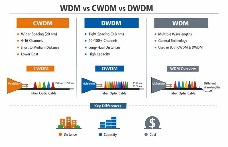
Feiyi publishes both a general PM Filter WDM and discrete PM DWDM 3-port products. A filter WDM is a practical starting point when the project separates broader wavelength regions such as pump and signal bands. A DWDM device belongs to a denser wavelength-routing discussion where channel spacing or a specific channel plan is part of the requirement. The buyer should choose the product family from the wavelength architecture, not from the fact that both devices have three fiber leads.
| Feiyi PM WDM family | Buyer question before approval | Document that should control the order |
|---|---|---|
| Polarization Maintaining Filter WDM | Which broader pass/reflection bands must be separated? | Band-to-port map and loss/isolation limits |
| PM 1064 nm DWDM 3-Port Device | Which dense channel around the 1064 nm platform is required? | Channel definition, route, PM fiber and connector record |
| PM 1550 nm DWDM 3-Port Device | Which 1550 nm DWDM route belongs in the instrument? | Frequency/wavelength plan and port assignment |
| PM 2000 nm DWDM 3-Port Device | Is the optical platform specifically built around the 2 µm region? | Approved wavelength family and optical interface |
| PM 100G/200G DWDM 3-Port Device | Does the dense channel plan require the listed spacing family? | Channel-spacing and wavelength-to-port schedule |
A pump-and-signal optical path should not be documented like a dense channel add/drop path
Feiyi lists fiber optical amplifiers among the applications of its PM Filter WDM. In an amplifier-related design, the engineering problem may be combining or separating wavelength bands with different roles in the optical chain. The port map should therefore name those functions and identify the expected wavelength region on each side.
In a DWDM route, the channel identity itself becomes central. The same three-port symbol can represent a different purchasing problem, because the dense channel must agree with the rest of the network or instrument. Keeping those two use cases in separate internal part families prevents a filter-WDM drawing from being reused for a DWDM replacement merely because the package appears similar.
The PM fiber axis belongs in the WDM handoff, not in an installation note
Feiyi’s Filter WDM page lists a minimum extinction ratio of 18 dB, selectable fast- or slow-axis direction, and PM Panda fiber. That is a reminder that the WDM is part of a polarization-maintaining chain, not only a wavelength-selective chain. A good drawing carries both pieces of information.
A wavelength map can be correct while the polarization interface is wrong
Imagine a sensor where the WDM sends every wavelength to the correct port but one connector is keyed to a different PM axis convention than the rest of the chain. The wavelength routing can pass inspection while the system’s polarization performance degrades. That failure is easier to prevent when the port schedule and axis convention are approved together.
If the device is ordered with bare fiber, the splice or assembly process must preserve the intended PM orientation. If it is connectorized, the connector-key convention should be included in the order and receiving documentation. The buyer should not assume that “PM fiber” alone defines how the device will be rotationally aligned in the final instrument.
Return loss, directivity, and PDL define other boundaries of the filter-WDM build
Feiyi’s Filter WDM page publishes polarization-dependent loss below 0.1 dB, polarization-mode dispersion below 0.1 ps, directivity of at least 50 dB, return loss of at least 45 dB, and maximum power handling of 300 mW. These values describe different optical behaviors; they should not be collapsed into a single quality label.
A buyer should identify which limits are critical for the installed system and retain the manufacturer’s published limits for the chosen family. For example, a precision polarization-sensitive instrument may pay close attention to PDL and extinction ratio, while a routing architecture may be particularly sensitive to isolation and directivity. The same product can be evaluated from different system priorities without inventing new performance claims.
A PM WDM manufacturer should see the full passive chain when ports interact with other components
A PM WDM rarely operates alone. It may connect to a PM isolator protecting a laser, a PM circulator handling a reflected signal, a PM VOA controlling power, or a PM patch cord carrying the signal between modules. Each neighboring component adds its own insertion loss and interface assumptions. The WDM loss budget should therefore be evaluated inside the complete chain.
A reflected-signal sensor can use a WDM and circulator for different reasons
In a sensor, a PM 1550 nm Circulator may direct a returned signal to a receiver while a WDM separates wavelength bands. Those functions should remain distinct on the block diagram. The circulator routes according to propagation direction; the WDM routes according to wavelength. Combining them into one vague “three-port PM component” description makes troubleshooting much harder.
Feiyi’s existing article PM WDM Supplier Selection Starts With a Wavelength Map, Not a Channel Count explains the importance of a wavelength map. The manufacturing decision here goes further by deciding which Feiyi WDM family should own that map and which product record must be frozen for production.
Incoming PM WDM checks should reproduce the approved route at more than one relevant wavelength
Receiving inspection can begin by confirming the labeled ports and product identity, then launching the agreed wavelength into the common port and measuring the intended output route. If the application uses a pass band rather than a single line, the buyer can select representative points from the actual system band. Isolation should be checked against the unwanted route under the same defined setup.
For a PM build, the test setup should also preserve the agreed polarization orientation. Connector end faces should be inspected and cleaned before measurement so contamination is not confused with WDM insertion loss. If a bare-fiber unit is tested after splicing, the splice method and PM alignment used for the measurement should be recorded.
Feiyi’s public page does not state one universal shipping package for every PM WDM configuration. For customized or repeat OEM orders, the buyer can specify practical delivery details such as port identification and protection of the fiber leads without claiming a standard that is not published. The goal is to ensure that the wavelength-to-port identity survives from factory test through receiving and installation.
Prototype changes should be versioned at the wavelength-map level
During development, a project may change a source wavelength, move a monitor channel, or replace a broadband filter route with a denser DWDM option. Those changes should create a new revision of the wavelength map rather than only a new purchasing note. Otherwise, old cable labels and new WDM hardware can coexist under the same internal description, making the next build difficult to audit.
Distributors should not merge visually identical PM WDMs into one stock item
For a distributor, the safest stock identity is based on optical function: product family, wavelength or channel, port map, PM axis convention, connector, and lead format. Two compact three-port parts may use the same housing and still send different wavelengths to different ports. Keeping the optical route visible in the SKU and receiving label reduces the chance that a mechanically identical device is picked for the wrong customer system.
If the customer later changes only the connector or lead length, keep the approved wavelength map attached to the revision. If the wavelength plan changes, treat that as a new optical configuration and revalidate the relevant pass, reflection, or DWDM route rather than assuming the former acceptance data still apply.
Release a PM WDM order only after the product family and wavelength map agree
The most useful purchase record names the Feiyi product family, the operating or channel wavelengths, the common/pass/reflection or add/drop port assignment, the PM fiber and axis convention, connector or bare-fiber interface, lead length, and the loss/isolation values that will be checked. For the Filter WDM family, the published 0.8 dB pass/reflection insertion-loss limits, ≥25 dB isolation, ≥18 dB extinction ratio, and 300 mW power handling provide concrete reference points for the corresponding configurations.
Buyers can review the full PM WDM range before releasing the drawing. If the requirement is still described only as “PM WDM, three ports,” the product family has not been selected precisely enough. Once the filter or DWDM route, wavelength schedule, and PM interface are all explicit, the manufacturer can build against a definition that purchasing, test, and service teams can understand later.