Plan a Four-to-Eight-Channel Upgrade With a CWDM Multiplexer Manufacturer
Four working services do not automatically become eight working services when the multiplexer is replaced. The new unit must preserve the installed wavelengths, match the remote end and leave enough optical allowance for each route. Work with a CWDM multiplexer manufacturer from that service plan. Feiyi’s four-channel assembly, eight-channel assembly and sixteen-channel assembly are relevant starting points for access and transport networks. Confirm the actual center wavelengths and both ends of every service before choosing the larger channel count.
The expansion can concern an enterprise adding services over existing fiber, an access-network contractor or a distributor supplying paired mux/demux assemblies. The useful first document is the installed service-to-wavelength map. A list saying only “eight channels” leaves the most consequential compatibility question unanswered.
A CWDM multiplexer manufacturer needs the installed wavelengths before the expansion count
Feiyi’s family lists 20 nm channel spacing and wavelength selections of 1270–1610 nm or 1271–1611 nm. Those descriptions identify alternative nominal conventions; they do not establish that every ordered unit contains the full range or that any two units bearing a CWDM label are interchangeable. Specify the required subset and the actual center for each channel.
The ITU-T G.694.2 wavelength grid defines the standardized CWDM reference. The recommendation’s technical text distinguishes nominal centers from the bounds needed by a transmitter and optical filter. Use this distinction when checking an installed transceiver label against the proposed filter; do not declare compatibility from rounded names alone.
Legacy 1270 labels and 1271 nm centers require a tolerance check
A network may contain equipment labeled with the older round-number convention. Establish the transmitter’s actual specified wavelength interval and compare it with the proposed filter’s approved passband. A one-nanometer difference in labels is not proof of failure, but it is also not proof of compatibility. The relevant decision is whether the operating spectrum remains inside the acceptable transmission condition.
For the Feiyi mux/demux family, the channel passband entry is at least 13 nm at the −0.5 dB bandwidth condition. Keep that condition with the width: it does not mean unlimited low-loss transmission anywhere between neighboring channels. Request the selected channel centers and their applicable spectral limits for the supplied unit.
Four-to-eight-channel CWDM expansion should preserve each service’s optical allowance
The family lists insertion loss no greater than 1.5 dB for four channels and 2.5 dB for eight channels. At sixteen channels it distinguishes a low-loss option no greater than 3.5 dB and a standard option no greater than 4.5 dB. These entries show why adding ports can change the allowance on services that already operate.
If a link uses one selected four-channel multiplexer at one end and its corresponding demultiplexer at the other, their listed limits give a hypothetical 3 dB two-device subtotal. Using the eight-channel limits gives 5 dB. This is a catalog-based planning comparison, excluding other route losses; it is not a measurement or a guarantee of reach. Check the actual delivered configuration and both ends before using the subtotal.
| Proposed change | Existing-service question | Evidence needed before installation |
|---|---|---|
| Four to eight channels | Can every original receiver tolerate the revised two-ended allowance? | Selected per-channel loss limits and confirmed wavelength subset |
| Eight to sixteen channels | Is the low-loss or standard sixteen-channel option actually ordered? | Grade identity and a complete service route budget |
| Terminal replacement to an add/drop arrangement | Which services continue through the intermediate node? | Approved add, drop and express route drawing with their own losses |
Idle CWDM ports are reserved wavelengths rather than returned power
A larger assembly can reserve wavelength ports for later service additions. Leaving some unused does not turn the unit into the lower-loss four-channel configuration. Budget the purchased assembly for the active routes, then identify reserved ports so they are not mistaken for interchangeable connections during maintenance.
Imagine a contractor adding four services while the original four must remain operational. Before the cutover, verify the original transmitter wavelengths against the larger mux and its remote demux. Record the corresponding channel identities on both ends. Merely plugging the original patch leads into the first four available ports is unsafe if the new assembly has a different wavelength order.
Sixteen-channel low-loss and standard variants need distinct order identities
The sixteen-channel 3.5 and 4.5 dB limits should not be blended into one generic item. If the planned route needs the low-loss option, specify it explicitly and retain evidence of the supplied grade. A distributor should not promise the smaller value for an assembly identified only by its channel count.
Assess every occupied wavelength independently. Fiber attenuation and the installed transceiver condition can differ across the selected band, so the most favorable route does not prove all services will operate. A route that passed before expansion deserves its own revised allowance; the added channels should not be the only ones checked.
For a distributor preparing an eight-channel pair, retain the customer’s original four wavelength identities in the order and separately list the four additions. This prevents an assumption that the requested set is simply the first eight nominal channels in a standard range. If an available configuration includes different centers, present that difference before substitution rather than ask the installer to discover it during cutover.
A project engineer should also identify which original transceivers remain in service. A new filter pair does not change their spectral tolerances or receiver limits. If the planned expansion requires different transmitter centers, that is an equipment change to approve explicitly. The mux replacement and the transceiver substitution should not be hidden inside one broad channel-count request.
Rack-mounted CWDM changes the service interface rather than the grid
Feiyi’s CWDM mux/demux in a 1U rackmount offers an alternative packaging route for a network rack. Its ordering information distinguishes mux, demux and mux-plus-demux configurations. Establish which optical functions are included and how their common and channel connections appear on the front panel.
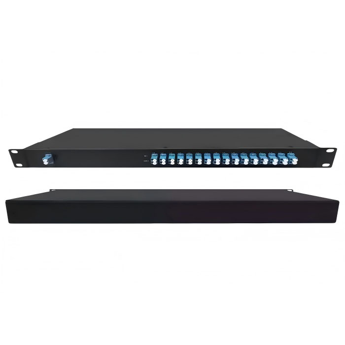
The ordering list also includes ABS-box and LGX arrangements. These choices concern mounting and connection access. A change from an ABS assembly to a front-panel rack does not justify changing the wavelength plan silently. Ask for the selected package drawing and ensure its ports correspond to the approved service map.
Common-port identification must survive the CWDM cutover
The common route carries the combined wavelengths; a channel port is associated with a selected wavelength. Preserve that distinction on the installation drawing and unit identification. A technician replacing a module should know which connection goes to the shared transmission fiber before disconnecting the old assembly.
The rack ordering information lists LC, SC and FC options in UPC and APC forms, together with 900 µm loose tube and 2 or 3 mm cable choices. Specify the mating interface for each supplied end. A desired front-panel layout should be confirmed separately from an assumed connector option, and the selected finish should agree with the receiving interface.
An intermediate CWDM OADM needs its own through-route definition
A network adding or dropping services at an intermediate site can examine Feiyi’s CWDM OADM module. This is a different topology from terminating all selected wavelengths at one endpoint. Identify which wavelengths leave or enter the node and which continue along the express route.
The OADM listing provides mux/demux-style channel data, including adjacent and non-adjacent isolation conditions. It does not establish every proposed express path or its cumulative loss. Request an approved route drawing and route-specific limits for the actual add/drop arrangement. Do not apply the terminal mux’s headline loss to every path through an intermediate node.
For an intermediate monitoring or service location, draw the eastbound and westbound routes if both are required. Specify whether the fiber plan is single-fiber or uses a fiber pair; a generic combined mux/demux title is not enough to determine that behavior. A system designer should approve how wavelengths are assigned to the directional routes.
An add/drop cutover should identify the continuing services that must be checked after the node is inserted. Measure those routes under the agreed reference conditions, not only the newly dropped channel. An OADM can make the local service reachable while adding an unacceptable condition to a service that continues farther along the line. The route drawing and budget should expose that dependency before installation.
The OADM family lists a different operating-temperature range from the ordinary terminal modules. Confirm the selected node’s environment separately rather than inheriting the terminal range. In a mixed installation, the common allowable conditions must satisfy every supplied component on the route; the widest individual range does not determine the whole link’s approval.
Adjacent-channel isolation is separate from the desired service transmission
The ordinary CWDM family lists isolation of at least 30 dB for adjacent channels and 40 dB for non-adjacent channels. Those are unwanted-transmission conditions. They should not be substituted for a selected channel’s insertion loss, nor used as proof of complete receiver performance under every combination of active transmitters.
During expansion, identify whether newly occupied wavelengths sit next to a sensitive service and whether the receiver needs an additional interference assessment. Confirm the filter’s relevant path and system conditions. A clean single-source loss test does not by itself evaluate all simultaneously active channels.
The expanded CWDM pair should be received as a matched service map
Request a unit-specific channel list with the port and center-wavelength identity retained for each end. For an eight-channel pair, receiving records should make it possible to trace each of the eight intended service routes from one side to the other. Separate mux and demux results where appropriate, then compare the combined route under the selected reference conditions.
Define whether acceptance includes the supplied connectors and the mating reference connections. The rack listing states specifications with connectors, but the order should still describe which interfaces and configuration are included. Do not add a generic connector allowance to a value already measured across the agreed supplied assembly. Keep the test boundary consistent with the budget used for expansion.
The family gives an operating range of −10 to +70 °C and a 300 mW maximum power-handling entry. Confirm the applicable power boundary for the combined common route when several sources are active. Individual low-power channels do not automatically establish the aggregate condition at every optical element. The component operating range also does not certify an outdoor cabinet.
Protect the ordered connector faces and retain channel identification during transport. For a paired delivery, label the assemblies so the installer can associate them with the approved endpoints. These are specific receiving requirements for a CWDM pair, not claims about a standard Feiyi shipping service or a fixed delivery period.
Feiyi’s customized wavelength-multiplexing discussion provides further context for configuration choices. Before approving the expansion, be able to point to the actual wavelength, remote port and remaining allowance for every original and added service. That record will make the new channel capacity usable when the cutover starts.