PM 1310nm Polarization Beam Splitter Manufacturer: Keep Both Receiver Channels Identifiable
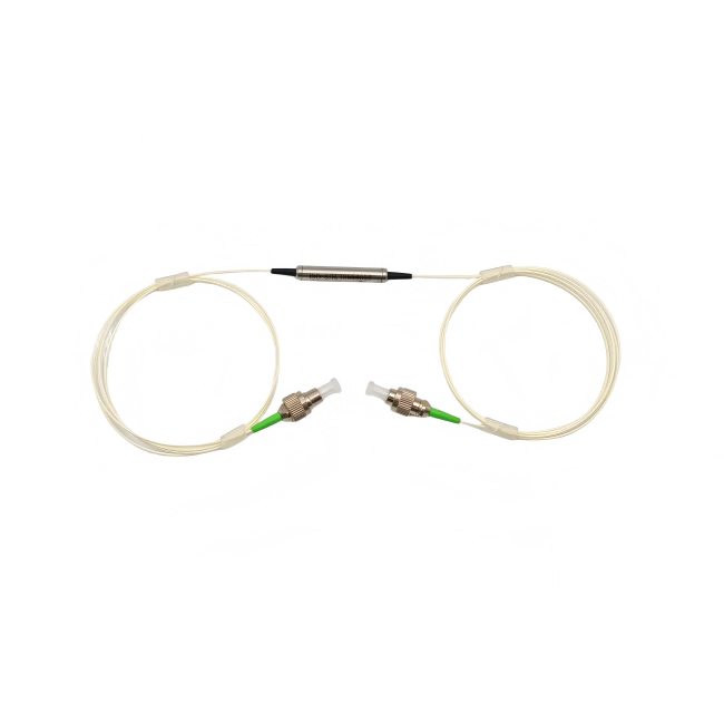
A PM 1310nm polarization beam splitter manufacturer should receive a diagram of the two polarization outputs before the buyer selects connector type. Feiyi’s PM 1310nm 1×2 Polarization Beam Combiner/Splitter operates at 1310 nm with a listed ±40 nm range and can be used in optical fiber gyros, coherent communication, fiber testing, sensors and research. In splitter use, the engineering job is to separate polarization states into two defined paths while preserving enough extinction ratio and keeping loss within the system budget.
A real purchase therefore starts with the receiver architecture. Which output represents which polarization state? Is each branch sent to a detector, another PM device or a measurement channel? What launch state and axis reference will be used for acceptance? A buyer who sends only “1310 nm PBS, FC/APC” leaves the most important optical identities unstated.
A PM 1310nm polarization beam splitter manufacturer needs both receiver-channel identities
In splitter operation, one input optical path becomes two polarization-defined outputs. The drawing should name those outputs according to the instrument’s meaning rather than leaving them as unlabeled fibers. In a coherent receiver, the channels may feed separate detection paths. In a fiber gyro or sensor, they may represent different polarization components used by the measurement architecture.
If the two outputs are accidentally swapped during assembly, the device itself can still look optically active while the instrument interprets the channels incorrectly. Port labels, axis references and detector names should travel together from the optical block diagram into the cable/harness drawing.
The slow-axis reference should remain visible from the splitter to the next PM interface
Feiyi lists slow-axis operation with fast-axis cutoff for this 1310 nm product. That makes the axis definition part of the delivered interface. If the outputs terminate in connectors, the connector key should be related to the approved axis convention. If the outputs are fusion-spliced, the splice instruction should preserve the intended polarization orientation.
A service technician should not have to infer the axis from cable color. Include the reference in the item record so a replacement can reproduce the original optical orientation.
The 1310 ± 40 nm range should be compared with the source spectrum before receiver alignment
Feiyi lists 1310 nm with a ±40 nm operating wavelength range. A source described simply as “1310 nm” can still have a particular tuning, bandwidth or drift condition, so the buyer should compare the actual spectrum with the component’s range. This is especially important in research instruments where the source may be changed without changing the rest of the receiver.
DK Photonics’ 1310 nm polarization beam combiner/splitter documentation is a useful industry reference showing that wavelength range, insertion loss, extinction ratio, power and fiber configuration are all controlled variables for this component class. Its values are not Feiyi specifications; Feiyi acceptance should follow Feiyi’s current product data.
A broad 1310 nm source still needs an acceptance wavelength plan
If the instrument uses several wavelengths within the listed range, define where optical performance will be checked. A single room-temperature reading at nominal center wavelength does not automatically prove identical behavior across every wavelength the source can reach. The test plan should reflect the actual operating points that matter to the buyer.
Insertion loss and extinction ratio answer different questions in a polarization splitter
The Feiyi 1310 nm 1×2 page lists typical insertion loss of 0.4 dB and maximum insertion loss of 0.6 dB. It also lists a minimum extinction ratio of 22 dB at 23 °C for the PM fiber type and return loss of 50 dB. Low insertion loss protects the available optical power; extinction ratio indicates how well the selected polarization channel is separated from the unwanted one. Neither metric replaces the other.
A receiver can have adequate optical power but poor polarization separation, or excellent separation but too much total loss elsewhere in the path. Put loss and extinction ratio on separate receiving lines so a pass/fail result cannot hide which behavior was actually measured.
Coherent receiver
Identify the two detector channels, source wavelength range, polarization reference and maximum allowed splitter loss before the cable layout is frozen.
Fiber gyro or sensor
Preserve axis identity through splices or connectors and keep the two polarization outputs mapped to the measurement channels used by the instrument.
SM-28E and PM1300-XP options should be assigned by port function
Feiyi lists SM-28E or PM1300-XP as fiber options for the input/output configuration. A buyer should identify which ports require PM fiber and whether any standard single-mode interface is intentional. Do not assume that every pigtail should be PM simply because the product is in the PM beam-combiner/splitter family.
This is particularly important when the splitter connects a standard single-mode source path to PM receiver branches, or when all ports must preserve a controlled polarization state. The supplier should receive the port-by-port fiber requirement. If a transition between SMF and PM fiber is part of the design, treat it as an engineered interface rather than a hidden assembly choice.
Fiber type changes should trigger a new axis and splice review
A prototype may use connectors for easy rearrangement and a production model may move to fusion splices. That change can reduce the number of mated interfaces but also changes how polarization alignment is established. Update the drawing and acceptance method when the fiber interface changes rather than carrying forward the old connector-based axis assumption.
The listed power choices from 0.3 W to 10 W should follow the actual 1310 nm location
Feiyi’s ordering information lists average-power options of 0.3, 1, 2, 5 and 10 W. The selected power class should match the optical power at the beam splitter’s installed location, including expected margin. A laboratory test at low source power does not qualify a later 10 W configuration unless that specific build and interface are confirmed.
Connector choice matters more as power rises. Feiyi lists bare fiber and common FC/SC connector options. The exact allowed power for the selected termination should be confirmed for the quoted build; do not assume every connectorized option supports the highest family power simply because 10 W appears in the ordering list.
A high-power splitter should be qualified with the same pigtail and termination used in production
If engineering tests a bare-fiber sample and production adds connectors, the optical interface has changed. Conversely, a connectorized prototype that moves to spliced pigtails should be re-baselined at the new reference planes. Keep the power class and termination together in the item identity.
The 5.5 mm cylindrical package fits differently from a 2×2 polarization beam device
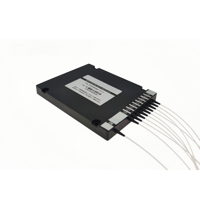
The Feiyi 1×2 1310 nm product lists cylindrical packages of about 5.5 mm diameter with L35 or L50 lengths. The site’s 2×2 beam combiner/splitter family uses a different rectangular package. A buyer deciding between 1×2 and 2×2 should therefore consider both topology and mechanical envelope rather than treating port count as a minor option.
For a compact sensor, allow room for the cylinder plus pigtail bends and connector service loops. The body can fit easily while fiber routing remains impossible. Put the actual package and fiber-exit plan into the mechanical review.

A polarization beam splitter should not be replaced by a 1310 nm power coupler
Feiyi’s PM 1310/1550nm Coupler divides optical power according to a coupling ratio. The polarization beam splitter separates polarization states. Those jobs can both produce two output fibers, but the underlying selection logic is different. A 50/50 coupler does not automatically produce the two orthogonal polarization channels a PBS is designed to provide.
The same distinction applies to a PM 1310nm Circulator, which routes light by direction, and a PM 1310nm In-Line Polarizer, which selects a polarization state. The BOM should name the optical function so a purchasing substitution cannot be made solely from wavelength and port count.
Receiver troubleshooting should verify channel identity before blaming the extinction ratio
If one detector channel looks weak or carries the unexpected signal, confirm that the two output fibers have not been swapped and that the source polarization is launched as intended. A routing error can mimic poor splitter performance. Verify the physical map and axis reference before concluding that the component’s extinction ratio is outside specification.
Production drawings should distinguish splitter direction from combiner direction even when the same device is reversible
Polarization beam combiner/splitter devices can often be used in either direction, but the assembled instrument still has one intended signal flow. A manufacturer drawing should show which port is the common path and which two ports are the polarization channels for the buyer’s application. That prevents an assembler from treating the device as a symmetric three-fiber junction and choosing lead orientation only for mechanical convenience.
For splitter use, the two output branches should be labeled by the receiver or measurement function they serve. If the same Feiyi product is later reused as a combiner in another instrument, create a separate controlled configuration or drawing rather than assuming the old splitter labels remain meaningful.
A channel-name convention should survive from optics to software and service documentation
Coherent receivers and sensing systems often assign software names to the two optical channels. Tie those names to the physical pigtails in the build record. If software calls them Channel X and Channel Y while the optical drawing calls them Port 1 and Port 2, include a cross-reference. That small step prevents a service replacement from restoring the hardware but swapping the signal interpretation.
For a distributor supplying preconfigured assemblies, keep any customer-specific channel labeling separate from the manufacturer product name. The product identity should still contain wavelength, topology and optical specification, while the application label tells the installer where each branch belongs.
Receiving inspection should preserve both channels as separate measurement records
For the first approved lot, record insertion loss for the relevant optical path, return loss if required by the system, and the polarization separation under the agreed launch condition. Keep the two output identities in the data file. Averaging the channels together can hide an assembly error in one branch.
Feiyi lists operating temperature from -10 to +75 °C and storage from -40 to +85 °C. If the receiver is intended for a wide thermal environment, include the required operating range in qualification. Do not assume that a room-temperature extinction-ratio check alone represents every installed condition.
Repeat 1310 nm orders should preserve the two-channel map that the receiver software expects
Once the splitter is integrated, retain the 1310 ± 40 nm range, 1×2 topology, output-channel identities, fiber configuration, slow-axis reference, insertion-loss limit, minimum extinction ratio, power class, connector/splice condition, pigtail length and package in one controlled record. That is the information a manufacturer can reproduce and a receiver team can verify.
Feiyi’s polarization beam splitter supplier article provides broader receiver-channel context, while the exact 1310 nm product page should remain the source for Feiyi’s current options. The purchase should be released only when the two receiver channels are identifiable without relying on cable position or an undocumented lab setup.
Keep the approved channel map with the receiver calibration and replacement record. If a future redesign changes connector type, power level or fiber choice, repeat the channel-identity review before assuming the previous splitter configuration remains interchangeable.
For receiving, photograph the port labels before installation so the accepted optical mapping can be reconstructed during later maintenance without disturbing adjacent PM fibers.