What a Multimode Fiber Collimator Supplier Needs for a 200 mm Optical Assembly
The light looks acceptable beside the fiber, yet too little reaches the receiver across the instrument. That is a useful starting problem for an equipment builder working with a multimode fiber collimator supplier: define the illumination at the receiving plane, rather than ordering a part by distance alone. Feiyi’s multimode collimator with WD 200 mm lists 50/125 fiber and 850/1310 nm operation. It is a candidate for a longer multimode free-space interface, provided the source launch and receiving optics are compatible with the selected configuration.
Before requesting a sample, draw the path from the source connector to the receiving aperture. Include the optical gap, the fiber feeding the collimator and anything that clips or redirects the beam. An instrument integrator should be able to explain how much light must arrive at that aperture and under which source condition. Without that information, a working-distance label can conceal the actual reason an assembly fails.
A 200 mm multimode optical path is a collection problem
At 200 mm, the downstream optics become part of the decision. Feiyi’s product table defines working distance but does not supply a complete beam profile for every possible input condition. The buyer must therefore distinguish a catalog configuration from a prediction that all emitted power enters a particular detector or lens.
Consider a builder adding a fiber-fed illumination channel to a measurement fixture. The receiver housing may leave space for only a small aperture. Even if the collimator transmits the expected power, part of that light can fall outside the accepted area. Increasing source power would not resolve whether the optical distribution is suitable, and could create a different operating condition from the approved sample.
50/125 fiber does not define the multimode launch by itself
The core and cladding dimensions identify the fiber geometry, but the way light enters that fiber determines which guided modes are excited. Describe the source type, coupling arrangement, intermediate leads and connectors used before the collimator. A launch established in the laboratory can differ from the launch produced by the intended module inside the finished equipment.
For background on this distinction, Thorlabs’ multimode beam study demonstrates that changing the input arrangement changes the output distribution. The lesson for this purchase is to preserve launch conditions during comparison, not to borrow another manufacturer’s beam shapes or measurements as Feiyi performance.
A supplier evaluation should consequently identify what is held constant between samples. If one candidate is tested with the production source and another with a conveniently available laboratory source, the measured difference cannot confidently be assigned to the collimator. Record the source, lead and receiver arrangement together with the part configuration.
The receiving aperture must be located at the agreed 200 mm plane
Specify where the working distance begins and where the receiver is measured. A lens mount, front window and detector surface can occupy three different axial positions. If the drawing names only the detector position while the actual acceptance test uses the window, the distance requirement has changed without anyone deliberately changing the purchase specification.
Keep the aperture size and position visible in the sample request. A camera view of the beam can help locate clipping or an offset, while an appropriately defined power measurement establishes collected light. Neither should be replaced with an unexplained statement that the output looks bright. The receiver’s job determines which observable quantity is useful.
For a fixture with several interchangeable receiver heads, qualify the receiving head with the smallest usable aperture first. A sample that works with a large bench detector may give an optimistic impression because that detector collects light the compact head cannot use. Record the receiving lens or detector configuration by its actual mechanical interface, so a later head change does not silently preserve an acceptance limit established with different collection optics.
Small alignment adjustments are also worth distinguishing from a configuration change. If the assembly needs substantial repositioning to recover collected power after being installed, determine whether the fixture provides that adjustment in production. An alignment achieved on a laboratory stage is not a repeatable mounting process unless the equipment has equivalent degrees of freedom. That distinction matters particularly when the 200 mm optical gap is already fixed by the instrument chassis.
Read the multimode collimator table as one configuration
Feiyi lists the WD 200 mm multimode product with insertion loss no more than 3 dB, return loss of at least 30 dB, a 2.2 ± 0.1 m fiber length and a 2.4 × 16 mm body. The values describe the listed product conditions. They should not be mixed with the single-mode table to produce a more attractive but unsupported purchase description.

850 nm and 1310 nm approval should use the selected source
The product identifies 850 and 1310 nm options, so write the actual operating wavelength into the order. A buyer qualifying an 850 nm instrument should not accept a 1310 nm demonstration as evidence of the same installed behavior. The optics, launched distribution and detector response must be considered at the wavelength the instrument will use.
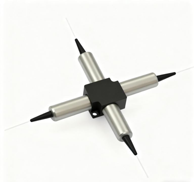
If a distributor serves both wavelength families, separate them in the item description and receiving records. The housing photograph is shared across several Feiyi collimator listings, so appearance is a poor inventory identifier. A label that records fiber type and wavelength is more useful than a cabinet location containing visually similar cylinders.
Connectorless loss and connectorized instrument loss are different boundaries
The multimode listing states that the measurements are made at 25°C without connectors and that connectors can change loss with wavelength. Decide whether receiving inspection measures the loose assembly, a connectorized assembly or a complete instrument path. Keep that reference boundary in the order and in the acceptance report.
Suppose the instrument builder receives a connectorized collimator and tests it through another patch lead. The resulting path includes connections that may not belong to the published component value. Inspection, cleaning and the selected reference method should be resolved before deciding that the optical assembly is defective. Conversely, excluding a connection that the finished instrument relies on can hide a real system loss.
For a return-loss requirement, identify the launch end and what is connected beyond the free-space path. The table’s value is not a statement about every window, detector or target that may reflect light back into the finished apparatus. If the source needs a particular return environment, include that environment in the engineering qualification.
Change the collimator family only when the optical task changes
The nearby products in Feiyi’s range are useful alternatives, but each changes a physical part of the design. Use them to decide what the instrument needs, rather than treating every collimator as an interchangeable means of extending a fiber.
The multimode body’s listed 16 mm length also needs its own mounting review. The dedicated single-mode version is listed at 14 mm, despite a similar diameter. A shared photograph or sleeve diameter cannot establish identical axial engagement, fiber-exit clearance or lens position. Preserve the ordered body drawing when preparing the mounting pocket.
The single-mode WD 200 mm product lists G657A1 fiber and 1310/1550 nm operation. It is relevant when the source and optical system are genuinely single-mode. Its lower listed insertion-loss number cannot establish that it is the better replacement for a 50/125 multimode channel, because changing the guided field changes the system being evaluated.
The coaxial collimator addresses a much shorter listed 5–10 mm working distance. Consider it when the receiver sits close to the optical head and mechanical compactness drives the layout. It should leave the comparison when the receiving geometry actually requires the long gap; a short-distance assembly should not inherit the 200 mm specification.
The single-fiber collimator range offers a broader configuration discussion involving lens choice, working distance and termination. An equipment designer with a different gap or interface can use that route to define a suitable build. The final configuration still needs a specific wavelength and fiber, rather than approval of the whole family by name.
These alternatives also affect purchasing documents. If an engineer changes from the dedicated WD 200 mm multimode part to a different configured collimator, retain the new drawing and measurement conditions with the order. Leaving the original item name on the purchase line can cause the supplier or receiving team to rebuild the earlier arrangement.
Qualify the multimode assembly in the order it will be installed
A sensible trial moves from an unmounted sample to the final mechanical arrangement while preserving the optical launch. Establish the source setting and receiving plane first. Examine collected power and beam placement with the collimator free of mounting loads. Then fit the body into the intended holder and route the pigtail as it will sit in service.
- Fix the selected wavelength and launch lead before comparing samples.
- Place the receiver at the agreed working-distance datum.
- Separate total emitted light from light collected by the receiving aperture.
- Repeat the observation after mounting and pigtail routing.
- Investigate changes in the mount or input condition before changing the collimator specification.
This sequence is a proposed buyer qualification, not a report of tests performed on a customer project. It keeps the dominant uncertainty visible: the supplier is furnishing an optical assembly, while the finished instrument determines how that assembly is illuminated and how its output is used.
The 0.5 W power entry should be checked against the actual input conditions. Do not interpret it as a separate pulse-energy or peak-power guarantee. The operating-temperature range of −20 to +75°C is also a catalog boundary, rather than proof of the installed fixture’s performance after repeated temperature changes. Any application-specific exposure belongs in the agreed approval procedure.
The 2.2 m pigtail needs an equipment route before a packing request
The listed 2.2 ± 0.1 m fiber length can be useful when the optical head and its connector are separated inside an instrument. Mark the length datum and the required termination, then check that the pigtail can be secured without pushing or pulling on the small lens body. An extra service loop should have a planned location.
For transport, agree how the collimator and fiber are supported independently. The optical face should remain protected from loose particles, and the pigtail should not be allowed to swing against the body. If receiving staff will remove a protective element before mounting, identify that element in the assembly instructions. These instructions describe what the order needs; they do not assert a packing method or delivery time that Feiyi has not documented.
A broader discussion of fiber choices is available in Feiyi’s single-mode, multimode and PM fiber comparison. For this purchase, keep the immediate approval narrow: the selected 50/125 launch must deliver the required light at the actual 200 mm receiving plane. A sample that meets that condition inside the intended mount is more meaningful than a brighter-looking beam tested with a different source.