Rack Mount EDFA Supplier: Place the Amplifier and Monitoring Ports in the Rack Plan
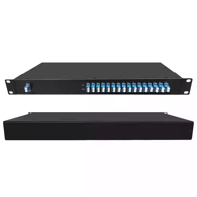
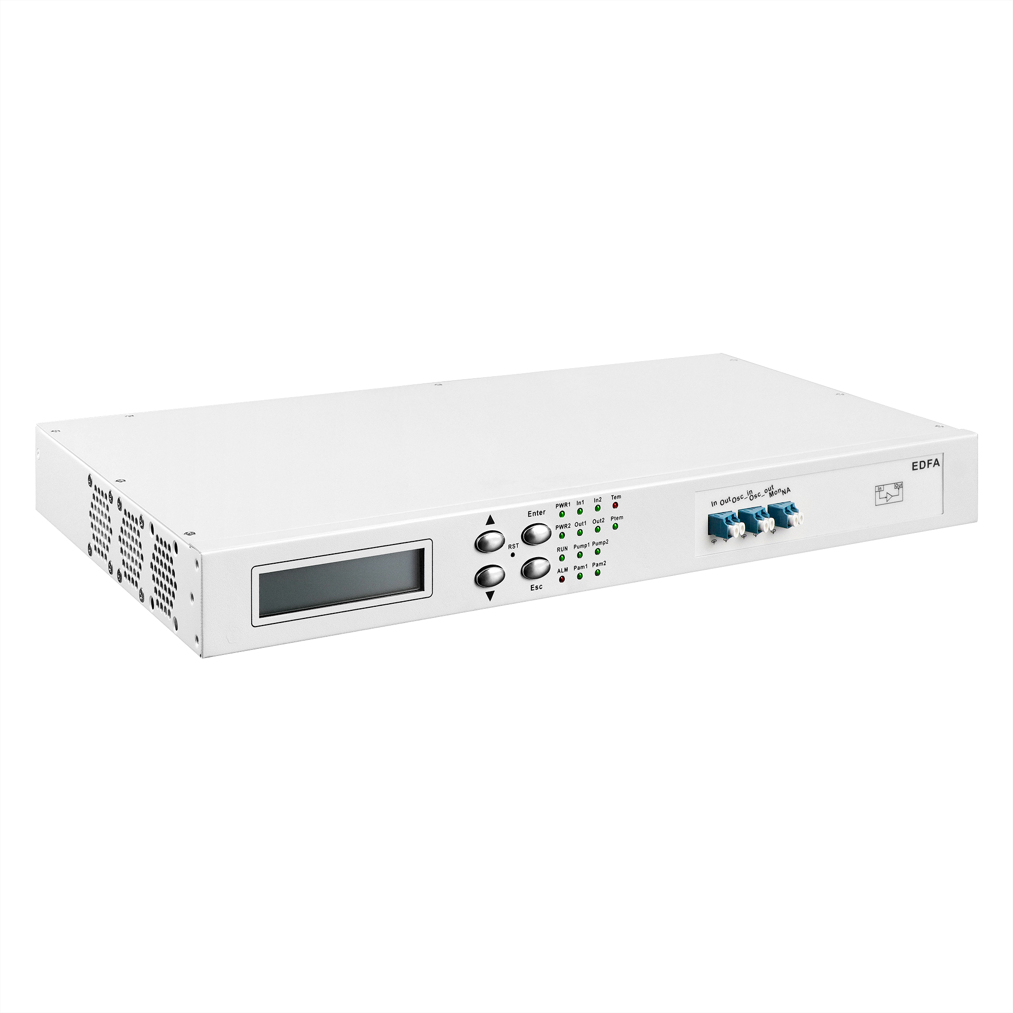
The amplifier arrives before the rack team has decided whether it is boosting the transmitter, compensating an intermediate span or improving the receiver input. A rack mount EDFA supplier needs that decision first. Feiyi’s 1U chassis-based EDFA describes C-band DWDM amplification, monitoring ports and selectable operating modes. For network integrators and equipment buyers, start with the amplifier position, input conditions and required output, then confirm the exact configuration and its connections before allocating the rack space.
EDFA means erbium-doped fiber amplifier. The supplied equipment amplifies an admitted optical signal; it does not correct every impairment of a long link or convert a mismatched wavelength plan into a compatible one. A useful order connects the intended optical role to the management behavior, so the rack can be commissioned without guessing what each port and control setting should do.
Place the rack mount EDFA at the optical role it must perform
Feiyi’s application table distinguishes BA power amplification at the transmitting end, LA line amplification between nodes and PA preamplification at the terminal. Each location gives the equipment a different input and output problem. The buyer should identify that role before selecting a gain or comparing the two optical columns shown in the product specifications.
| Position described by Feiyi | Starting condition to establish | Question for the selected configuration |
|---|---|---|
| BA at the transmitter | Combined signal reaching the amplifier | Required launched output and limits |
| LA along the route | Signal after the preceding span | Gain behavior and downstream loading |
| PA near the terminal | Signal arriving at the receiving node | Receiver input and noise-related requirements |
A C-band amplifier cannot inherit an O-band AWG route
The EDFA listing gives a standard operating range of 1529–1561 nm and an extended range of 1528–1568 nm. Select the relevant approved configuration, then check every transmitted channel against it. The product is not evidence of amplification near 1290 nm, even if an O-band module is available from the same supplier.
An integrator upgrading a rack should recover the channel plan rather than retain an amplifier because its case fits the available space. Feiyi’s 40-channel 100 GHz AWG can be part of a DWDM routing review, but the particular AWG plan and amplifier band still have to agree. Product-family names cannot replace that comparison.
The OBA and OPA columns need an approved equipment identity
The optical table presents OBA and OPA columns, including different minimum input levels, output limits and maximum gains. Obtain the approved specification for the required amplifier role instead of deriving a build from the most favorable value in each column. The application role and ordered equipment identifier should agree even where a short table label is ambiguous.
For example, the published columns include output values of +20 and +16 dBm and maximum gain values of 17 and 20 dB. Those values do not form one freely selectable combination. Keep input, output, gain and operating band connected to the selected configuration. A requirement outside that configuration should prompt a different approved build, not a rewritten catalog limit.
The minimum-input entries also differ, at −22 and −32 dBm in the corresponding columns. A buyer compensating a weak received signal should identify which approved configuration admits that input condition. Selecting the highest gain number without checking the associated input and output conditions leaves the intended operating point undefined.
Feiyi describes amplification of up to 48 channels at 100 GHz or 96 channels at 50 GHz within the stated C-band arrangement. This is a reason to identify the populated optical plan, not a guarantee that any set of 96 wavelengths is admitted. Preserve the actual centers and combined input conditions with the amplifier configuration. The published gain-flatness and noise-related entries also require their applicable measurement conditions before being treated as evidence for a fully populated link.
For a receiver-end trial, record whether the acceptance result concerns amplifier output alone or the receiver after its intervening filters and connectors. A successful chassis-level measurement cannot account for unmeasured losses introduced farther downstream. That distinction helps the supplier and integrator locate an unexpected receiver reading without changing the amplifier purchase prematurely.
AGC and APC must match the rack’s control objective
The product describes constant-gain AGC, constant-output APC and constant-current ACC settings through network management. Select the mode according to the optical behavior the rack needs. An engineer should describe what is supposed to remain controlled when the input changes, rather than treating the mode as a checkbox that commissioning staff can choose later.
AGC holds a gain target while the input condition changes
Automatic gain control is relevant when the intended amplification relationship is the controlled quantity. Define the input conditions under which the rack must operate and the approved gain range. A configured gain value is not permission to exceed the output or input limits of the selected equipment.
A network buyer adding or removing DWDM channels should discuss the populated-channel conditions with the amplifier supplier. The total input reaching the common path may change as the channel population changes. Commissioning should therefore preserve the actual operating scenario in the approval record, rather than testing only one convenient channel and generalizing the result to every population.
APC controls output power but does not define every channel’s power
Automatic power control concerns the stated output target. Identify the measurement point and whether the requirement concerns combined optical power or another specified quantity. An aggregate output setting does not establish identical power on every DWDM channel. The approved channel plan and input distribution remain relevant.
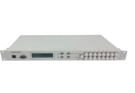
FS’s network-element configuration manual illustrates the distinction between amplifier operating modes. Its settings and hardware limits belong to FS equipment. Use the control concepts to frame the Feiyi approval request, not to populate Feiyi configuration values or imply shared management software.
If a purchasing team needs a spare EDFA for several sites, record the mode and configuration used at each site. A spare that can physically occupy the rack slot may still need different approved settings. Dispatching it with an unexplained factory-default mode can create a commissioning error unrelated to its optical manufacture.
Separate signal ports, monitoring ports and OSC connections
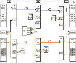
Feiyi identifies IN and OUT as the signal path, MON as an optical monitoring port and OSC_IN/OSC_OUT for the supervisory-channel arrangement. Map these interfaces on the rack drawing before installation. They serve different purposes and should not be treated as interchangeable optical access points.
MON needs a defined relationship to the measured output
A monitoring connection gives access to a measurement path, but the reading must be interpreted according to the approved port relationship. Ask what the MON result represents and which equipment is required to evaluate it. Do not assume that the value read at MON is numerically identical to the power at OUT without a defined relationship.
An installation team may use a power meter at MON to avoid disturbing the main optical route. Retain the measurement configuration and any applicable correction with the commissioning record. A later maintenance technician should be able to distinguish an actual output change from a different meter connection or an undocumented interpretation of the monitor port.
OSC transmit and receive directions belong on the management drawing
The product’s connection description associates supervisory-channel ports with network-management transmit and receive connections. Recover the exact arrangement for the selected amplifier position. A signal route can be optically functional while the supervisory link is wired incorrectly, leaving the operator without the monitoring behavior expected from the purchased equipment.
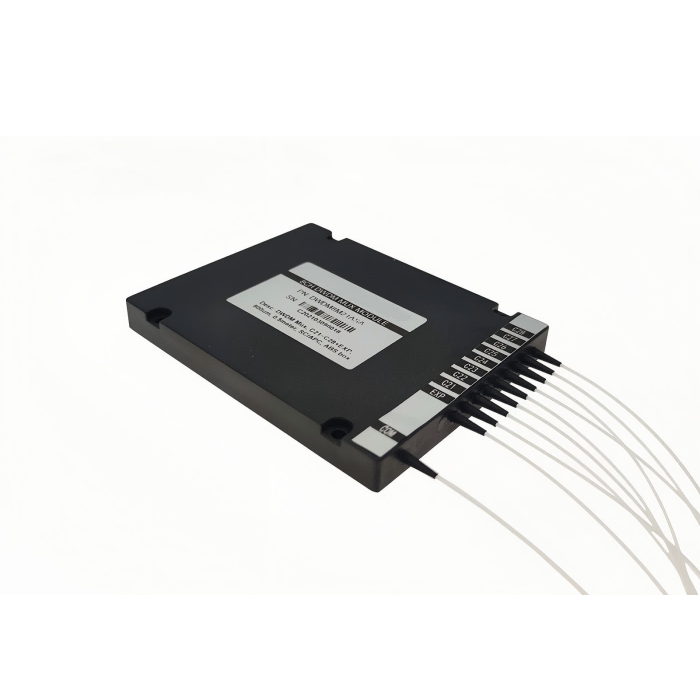
Feiyi’s DWDM module and three-port DWDM device offer wavelength-routing functions that may enter the wider rack design. Keep their pass, reflection or multiplexing routes distinct from the EDFA’s management connections. A wavelength-filter port label does not define an amplifier’s OSC direction.
Bring alarm and recovery behavior into the EDFA commissioning trial
The listing describes monitoring of input and output power, pump condition and temperature, together with configurable thresholds. It also describes an input-low alarm condition that turns the pump off and references recovery-related settings. Define the intended response before relying on those functions in a network-protection arrangement.
An integrator operating a remotely managed node should identify what the controller reports after input loss and how the equipment returns to the approved operating state. A display that shows normal power during a stable bench trial does not establish the behavior after a lost signal or control interruption. Exercise the agreed conditions with the ordered configuration before deployment.
Keep the alarm thresholds distinct from optical operating limits. A threshold selected for an operational warning does not necessarily define the safe maximum input or output. If several thresholds appear in the management interface, document their intended meanings and units. A dB gain setting and a dBm power setting describe different quantities.
The page describes an eye-protection mode intended to reduce output during installation or fault work. Treat it as a device function requiring a defined procedure, not a substitute for the equipment’s laser-safety controls. Technicians still need to identify the operating optical path and follow the applicable handling instructions before disconnecting or inspecting a fiber.
Internal WDM components are not substitutes for a complete rack EDFA
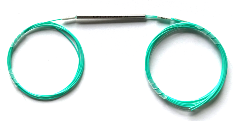
Feiyi’s 980/1550 and 1480/1550 FWDM devices address pump and signal wavelength routing in suitable assemblies. They are relevant to an OEM discussing internal optical construction, but do not perform the complete amplification, control and monitoring functions of the rack instrument.
A distributor should consequently separate component purchases from complete-equipment purchases. An engineer seeking a pump/signal filter needs the corresponding port fiber and wavelength bands. A rack operator seeking an EDFA needs the amplifier configuration, management behavior and commissioning evidence. Confusing these scopes can create an apparently cheaper quotation that omits the required operational functions.
The same distinction applies to documents. A loss table for a passive filter cannot establish the rack EDFA’s gain, noise-related behavior or alarm response. Conversely, a chassis-level description does not approve every internal component for an OEM’s independent amplifier design. Retain the delivered-object boundary in the purchase record.
Receive the 1U EDFA as configured optical equipment
For shipping and incoming inspection, agree protection for the chassis, optical ports and supplied accessories. Identify whether fiber leads, management connections or other items belong to the delivered configuration. These are order-specific requirements; the available product information does not establish a universal packing method, stock position or dispatch promise.
Before applying power in the receiving area, compare the equipment identifier and interface markings with the approved drawing. Establish which connector polish mates with the optical ports; the listing identifies LC/UPC with customization available. A proposed connector change must be recorded rather than assumed from the case appearance.
The wider EDFA technology explanation provides background on amplification. The purchasing decision here is more concrete: approve the selected role, operating mode and port map together. Release the rack build when the commissioning team can trace the actual input to the intended output and supervisory connections without choosing an amplifier function on the fly.