Replacing a DWDM Line Card Optic With a 10G DWDM XFP Transceiver Supplier
Replacing an optic on a DWDM line card should not change the circuit by accident. A maintenance team working with a 10G DWDM XFP transceiver supplier needs to preserve the XFP host interface, configured ITU channel and far-end receiving conditions. Feiyi’s 10G DWDM XFP transceiver is a candidate for XFP-based 10G equipment, with a listed 9.95–11.3 Gb/s family range and 40 km/80 km ordering options. Begin with the card and installed optical route, then confirm the specific supplied module.
The largest replacement risks are often hidden in abbreviated descriptions: “10G,” “80 km,” or an ITU channel number without its full configured identity. Each describes part of the requirement. None establishes a complete drop-in replacement. The following review follows the possible substitution errors from the line card to the receiver, so that an urgent order preserves the service it is intended to restore.
Recover the DWDM XFP circuit identity before accepting a substitute
The useful starting document is the installed circuit record. Recover the host card, service mode, optic format, configured center frequency or wavelength, passive channel and opposite endpoint. If the existing module failed before its label could be read, use the approved equipment and fiber records to recover the identity. Do not infer the affected channel from an adjacent port.
The XFP footprint should survive the purchasing shorthand
Feiyi describes a hot-pluggable XFP footprint, XFI and line-side loopback, +3.3 V and +1.8 V power supplies and operation without a reference clock. These are relevant host-interface facts. The page’s “XFP+” naming should not be taken to mean physical interchangeability with SFP+. Preserve the required XFP interface in the order description.
A maintenance contractor may receive a proposed 10G spare with a similar wavelength and metal housing. Before comparing its reach, check whether it actually belongs to the host format. Replacing the card or adding another interface device would be a different engineering change, with a different scope from restoring the original optic.
9.95–11.3 Gb/s does not approve every line-card application
The family rate range and application list provide an initial screen. Confirm that the selected configuration operates in the service mode used by the card. A sample that runs a convenient 10G test mode is not automatically qualified for a different transport application. The host evaluation should identify the actual operating mode and equipment configuration.
Where a distributor supplies several equipment generations, separate the approved spare records by host format and service. A channel-specific XFP can be useful stock for one configuration while remaining unsuitable for a newer SFP+ installation. Maintain those boundaries even when both network services use the same line-side wavelength.
Make the 10G DWDM XFP ordering row a configured optical specification
Feiyi lists XKXFD-XX96-80BD at 10G and 80 km, with DWDM ITU-grid channels 17–61, EML/APD and LC/PC. The XKXFD-XX96-40BD row is listed at 10G and 40 km, with the same channel range, EML/PIN and LC/PC. Each row has a DDM Y/N field. Confirm the selected channel, temperature version and diagnostic option for the actual supplied module.
The EML/APD and EML/PIN entries should remain associated with their respective rows. Do not merge them into a single receiver claim. The row names and distance categories do not publish the full transmitted-power range, sensitivity, overload or optical tolerance needed to approve a substitution.
| Proposed change | Risk that must be resolved | Evidence needed |
|---|---|---|
| 40 km row replaced by 80 km row | Receiver and transmitted-power conditions can differ | Configured optical limits for both endpoints |
| Same channel label, different passive assembly | Passband and route loss can differ | Frequency, filter map and accepted path budget |
| XFP replaced by a different module format | Host interface is no longer preserved | A separately approved equipment change |
| Different temperature or DDM option | The approved configuration is no longer identical | Version-specific technical and host confirmation |
ITU channels 17–61 describe available family choices
The listed channel range should not be described as proof that one unit is tunable across all those channels. Obtain the configured center and its permitted behavior. If the line card requires a tunable optic, that requirement needs explicit confirmation; the product’s family channel range alone does not establish it.
As a general reference, ITU-T G.694.1 defines the DWDM frequency grid. Use an unambiguous center-frequency record when reconciling module and filter labels. The recommendation does not supply the Feiyi module’s temperature stability, passband fit or host approval.
Protect the far-end receiver when the spare’s reach category changes
A distance category does not approve the power delivered to the remote receiver. The maximum received input matters on low-loss paths, while minimum received input matters on long or heavily filtered paths. Obtain the exact module limits and calculate both conditions. A longer-reach label is not automatically a safer substitute for the old configuration.
Suppose a field team restores a circuit using a spare first tested through a short bench lead. That bench arrangement has a different loss from the installed fiber and passive assemblies. It may need a different attenuation arrangement. Establish the permitted input range before the test, and distinguish the laboratory result from the deployed-circuit result.
For the installed route, identify fiber loss at the selected channel, the passive path at each end, connectors and splices. Preserve any approved reserve. If an external attenuator is proposed, define its value from the two-end limits and actual route, rather than from the 40 km or 80 km label alone.
A receiving substitution can also change the equipment’s diagnostic expectations. The Feiyi page names temperature monitoring and includes a diagnostic option in the ordering table. Confirm what the supplied version reports through the host. Do not interpret a general diagnostic feature as a guarantee of every optical reading or alarm used by the line card.
Keep the DWDM passive assembly inside the replacement decision
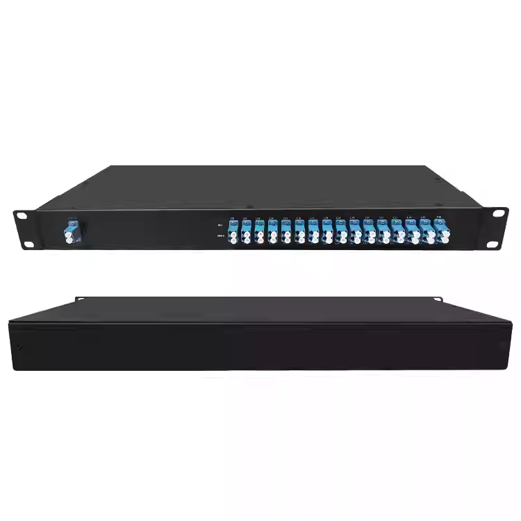
The Feiyi DWDM module represents the passive channel assembly that can sit between the XFP and the line fiber. Recover its configured port map and optical direction. The replacement’s center frequency must reach the intended far-end receiving path through that assembly, not simply fall somewhere within the transceiver family range.
A matching nominal center is the beginning of the passband review. Compare the configured optic’s relevant tolerance with the approved passive path under the intended operating conditions. If the passive assembly was changed during previous maintenance, use its current record instead of an original drawing that no longer describes the deployed route.
For a circuit carrying several services, confirm that testing the replacement will preserve the identity of the other channels. Label the removed and reconnected leads, and retain the affected port’s mapping. Exchanging fibers without that record can create a new channel problem while the original optic fault remains unresolved.

Use XFP loopback results to locate a fault, then restore normal operation
The listed XFI and line-side loopback features can support an equipment test when the host provides an approved procedure for them. Define which segment each mode examines. A loopback test can isolate a portion of the signal path, but it does not establish that every external filter, fiber connection and remote receiver has passed.
Record the module configuration, host service mode and loopback mode for each observation. Then return the equipment to normal operation and evaluate the full circuit. A service that appears healthy only while a loopback remains enabled is not restored. The handoff to the operating team should identify the final normal configuration.
If the host recognizes the optic but the normal service remains unavailable, inspect the channel mapping and receive-power condition before exchanging multiple parts. If the host does not recognize it, preserve the interface evidence for the supplier review. Those two failures point to different parts of the approval and should not be collapsed into one “bad module” label.
An equipment team should also decide how the module temperature observation will be interpreted. Feiyi lists an industrial −40 to +85°C option and refers to a commercial version. Confirm the commercial limits and the selected configuration on the approved sheet rather than importing values from another product page. Evaluate the actual module case conditions, especially in a populated line card.
When the replacement returns the service to operation, retain the module identifier and the passive port used for the final test. If a temporary connection or attenuation arrangement remains, identify it explicitly for the operating team. A later technician should be able to distinguish the restored circuit from the laboratory arrangement used to isolate the original fault.
For a receiver-related alarm, compare the actual received condition with the approved optical limits before assigning a cause. A dirty interface, wrong filter route or changed attenuation can alter that condition without changing the XFP’s configured wavelength. Preserve the original observations while investigating. Repeatedly exchanging modules without recording the route and power condition can consume spare stock while leaving the external problem unchanged.
Distinguish DWDM XFP stock from SFP+ and 2.5G SFP stock
The 10G DWDM SFP+ transceiver is relevant to an SFP+ host review. The 1.25G/2.5G DWDM SFP family addresses a different rate family. These products can appear on the same network inventory while belonging to distinct spare pools. Keep rate, format and configured channel visible in each stock line.
For a distributor, a useful substitution policy identifies which configurations engineering has actually approved. Avoid a broad equivalence group containing every DWDM module at a given wavelength. Such a group can hide changes in the host format, receiver limits and service mode. Store the applicable approval document with the configuration description.
Feiyi’s transceiver overview helps explain the network role. The practical maintenance record should go further by naming the XFP spare, installed card and exact receiving relationship that it preserves.
Deliver the approved XFP spare with its channel identity intact
Agree a packing list and module labels that preserve the selected frequency, format, temperature version and diagnostic choice. Request protection for the optical interface during shipment and storage. Those are requirements to agree for the actual order; the catalog does not establish a fixed shipping kit or guaranteed dispatch time.
When an alternative is offered because the original configuration is unavailable, compare it against the specific risks above. Do not authorize a different receiver row or module format solely because it can ship sooner. Identify which conditions have changed and obtain the corresponding host and optical approval.
The replacement is ready when the line card operates the intended service, the configured frequency follows the correct passive route and the far-end receiver remains within its approved input range. Preserve that result as the spare definition. A longer distance label can wait; restoring the original circuit without an unintended interface change is the immediate purchasing objective.