1625nm FWDM Supplier: Separate the Maintenance Test Path From Service Wavelengths
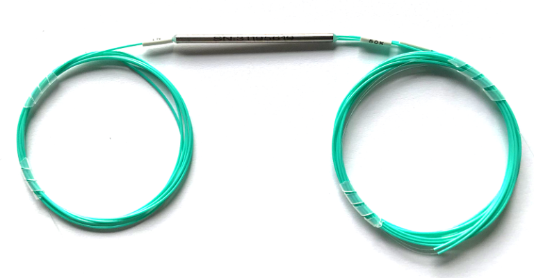
A maintenance team wants to observe a fiber path while service wavelengths remain in use. The first purchasing question is how the test light reaches the fiber and stays separated from the active equipment. A 1625nm FWDM supplier can provide part of that arrangement, but the filter alone does not approve a live-fiber test. Feiyi’s three-port FWDM device includes T1625 R1310/1490/1550 as a listed selection. Begin with that transmission/reflection assignment, then confirm the complete instrument, filter and receiver-protection design.
This product is relevant to instrument developers, network integrators and maintenance equipment buyers who need a defined test-wavelength route. Before selecting it, identify the service bands, the test instrument and which equipment must reject the test light. The word “1625” is an optical-band starting point, not a guarantee of non-disruptive operation on any deployed network.
Draw the 1625 nm test route and service route separately
In Feiyi’s T1625 R1310/1490/1550 option, T denotes the transmission wavelength and R the reflection wavelengths. The configured diagram should identify the common fiber, the transmission lead and the reflection lead. That map decides how the proposed test instrument and service equipment are connected. Do not infer port roles from the physical order of three leads.
T1625 R1310/1490/1550 is the relevant FWDM selection
The product lists this arrangement alongside other FWDM combinations, including T1650 R1310/1490/1550. Treat those as distinct selections. A buyer requiring 1625 nm should not receive a 1650 nm version simply because both are used in maintenance discussions. The instrument wavelength and the configured filter response need to agree.
The page also lists wavelength entries such as 1625±25 nm. Obtain the configured band and accepted optical limits for the ordered device rather than treating that family entry as proof of compatibility with every test instrument. The instrument’s required optical conditions and the complete service path remain part of the review.
Receiver protection belongs beyond the single filter
A listed reflection band does not independently establish that every active receiver is protected from injected test light. Identify the full path from the test port to each service interface, including any filters at the receiving equipment. Confirm the permitted optical conditions with the equipment and network design before approving an online test.
As an external engineering reference, EXFO’s OTDR/iOLM guide discusses filtered test ports and maintenance wavelengths for live-fiber applications. The distinction matters: a wavelength label does not, by itself, establish the complete filtered instrument and network arrangement.
A maintenance buyer adding a test access point to an existing service should recover the receiving-equipment requirements before ordering the filter. If those requirements are unknown, the unresolved item is the system’s test-light rejection and permitted operating condition. Choosing a product with a familiar maintenance wavelength does not close that gap.
A 1625nm FWDM supplier should explain both insertion-loss paths
Feiyi gives transmission insertion loss no greater than 0.80 dB and reflection insertion loss no greater than 0.60 dB for the three-port FWDM range. Keep these limits associated with the configured routes. In the proposed arrangement, the maintenance path and service path may traverse different entries; one generic filter-loss number would hide that distinction.
| Route to document | Published range entry | Question for the complete system |
|---|---|---|
| Transmission | Insertion loss ≤0.80 dB; isolation ≥30 dB | How does the configured test route affect the instrument measurement? |
| Reflection | Insertion loss ≤0.60 dB; isolation ≥15 dB | How does the service path retain its optical margin and rejection requirements? |
| Interfaces | Connectorless specifications; additional 0.2 dB per connector stated | Which delivered terminations are included in the accepted path? |
The transmission and reflection isolation entries are different. Obtain their measurement direction and wavelength conditions for the selected configuration. Do not use the ≥30 dB transmission figure as a universal rejection guarantee at every receiver connected to the assembly.
Connectorless FWDM limits need the delivered interface arrangement
The product states that its limits exclude connectors and notes an additional 0.2 dB loss per connector. Include the selected connectors in the network and instrument budget. A spliced bare-fiber device, a connectorized filter and a filter attached through an extra adapter are different acceptance arrangements.
For an instrument developer, retain the reference planes used when evaluating the test path. A measurement made through the whole test-access assembly includes more than the FWDM itself. Separate the passive-component result from the complete instrument result so that an extra connection is not mistaken for a change in the filter.
Review the service path before inserting a maintenance access point
Adding a filter can change the service loss even when the service wavelengths remain assigned to reflection. Evaluate the actual route and available margin before insertion. Identify each connector, splice and passive element involved rather than approving the change from the FWDM’s maximum loss alone.
Consider an integrator installing a test port in equipment whose fiber budget is already defined. The correct T1625 selection may satisfy the desired routing, yet the added service-path loss still needs approval. Keep the service budget and test-path requirement as separate calculations. Passing one does not automatically establish the other.
A field team replacing an existing FWDM has a different task: preserve the installed transmission/reflection assignment, connector polish and lead routing. If the old unit’s configuration cannot be recovered, obtain it from the equipment or assembly record before fitting a similarly shaped device. Three fibers leaving a tube do not identify the optical map.
Feiyi lists return loss at least 45 dB, directivity at least 55 dB and PDL no greater than 0.1 dB. These values help define a component review. They are not a service guarantee for the complete network and do not establish a PM fiber-axis specification. Evaluate the configured component against the application’s actual requirements.
Choose FWDM, CWDM and DWDM products for their distinct optical jobs
The 980/1550 and 1480/1550 FWDM range addresses different wavelength-band combinations, including amplifier pump/signal discussions. Its use of the FWDM name does not make it a substitute for T1625 R1310/1490/1550. Select the configured bands before comparing housings or connector options.
The three-port CWDM device is relevant to selected-channel routing on a CWDM grid. The three-port DWDM device provides narrow-channel options with 100 GHz and 200 GHz spacing. These products should be evaluated by their own bands and passbands, rather than treated as generic maintenance-wavelength filters.
The 8-channel CWDM mux/demux is an assembled channel-routing product. It may belong elsewhere in a network design, but its listing does not establish a dedicated 1625 nm test port. A buyer comparing a filter with a completed mux should preserve that difference in scope.
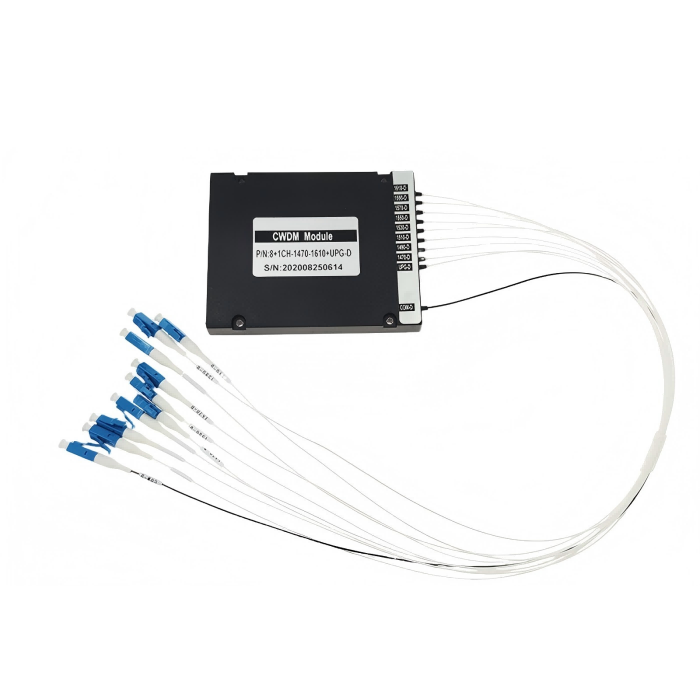
A wholesaler supporting both communication channels and test-access assemblies should therefore keep separate stock identities. The receiving description should contain the configured T/R bands, not only “three-port filter.” This reduces the chance that a channel-selection device is dispatched for a broad service-band maintenance arrangement.
Fit the FWDM into the enclosure without losing its port labels
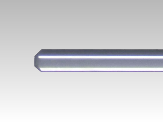
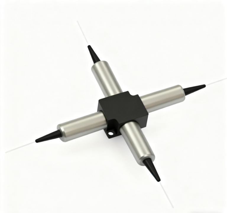
Feiyi lists Φ5.5 × 38 mm for 250 µm and 900 µm arrangements, and 90 × 20 × 10 mm for 2.0 mm and 3.0 mm options. Review the selected package with the actual lead routing and strain restraint. The smaller body is not automatically the easier installation if the equipment requires accessible, protected service connections.
The ordering information offers fiber lengths and connector choices including LC/UPC, LC/APC, SC and FC options. Specify the intended polish and mating arrangement for the configured test and service interfaces. A shared connector body does not remove the need to match the actual optical interface.
For a serviceable equipment enclosure, retain port labels after the cover is fitted. A technician should be able to identify the test and service connections without reconnecting the device experimentally. Confirm the lead-exit drawing and selected cable protection with the enclosure layout before approving the sample.
The product’s operating-temperature entry is −20 to +70°C. Evaluate the component location rather than only outdoor or room ambient. If the equipment specification requires additional environmental conditions, obtain the corresponding configured evidence; the optical table does not establish sealing, vibration or every thermal-cycle requirement.
The FWDM table also lists wavelength thermal stability no greater than 0.003 nm/°C and insertion-loss thermal stability no greater than 0.005 dB/°C. Keep those component entries separate from the complete network’s operating approval. They do not establish that every connected test instrument or service receiver behaves acceptably over the enclosure’s full temperature range.
For an OEM placing the device beside active electronics, identify the component’s expected local temperature and the accepted optical test conditions. If the housing or lead routing changes between the sample and production assembly, review whether the existing acceptance arrangement still represents the delivered equipment. The filter’s published package dimensions and thermal entries should be checked against that actual placement, rather than copied into an unqualified enclosure-level claim.
The receiving label should make the selected T1625 arrangement distinguishable from neighboring T1550 and T1650 selections in the same family. A technician fitting the device into a test-access assembly needs that identity before connection. Retaining the configured bands on the packaging and component record prevents a visually similar FWDM from being approved merely because it has the same three-lead structure.
Approve the maintenance procedure as well as the FWDM component
The sample plan should identify the instrument, configured filter, optical directions and permitted service conditions. Agree how component loss and isolation will be checked, and how the complete network’s test-light rejection will be verified. Keep these as separate results. A correct FWDM component is only one part of a qualified maintenance procedure.
Where live operation is intended, confirm the instrument’s filtered-port arrangement and the relevant receiving-equipment restrictions before connecting the test light. Where the system is not approved for live testing, plan the maintenance condition accordingly. Do not infer permission to inject a test pulse merely from the T1625 selection.
Feiyi’s FWDM technology discussion provides broader routing context. The practical approval here should retain the specific maintenance wavelength, service bands and connected equipment, rather than substituting a general FWDM explanation for system qualification.
Agree shipment protection and labels that preserve the configured T1625 R1310/1490/1550 identity through receiving and installation. Confirm dispatch timing for the actual package and termination arrangement. Neither the family’s customization statement nor a product image proves ready stock, a standard export pack or a guaranteed delivery period.
Order the filter once the transmission/reflection map is agreed. Approve the live-test procedure only when the instrument and receiving equipment are also covered by the design. Keeping those two decisions separate lets the buyer obtain the right 1625 nm component without making an unsupported promise about uninterrupted service.