Rack Mount Optical Switch Supplier: Integrating a 1U Multichannel Test Instrument
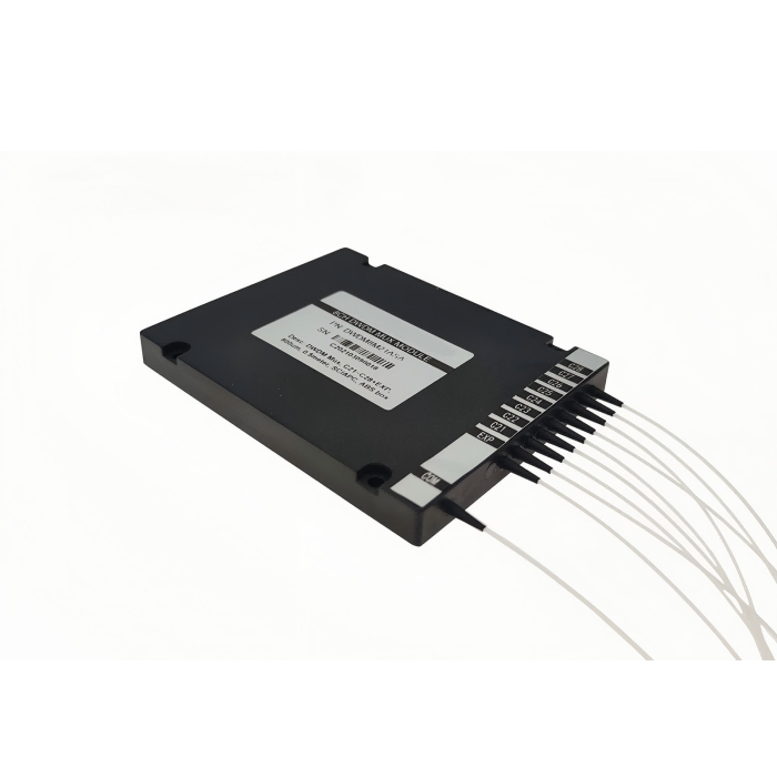
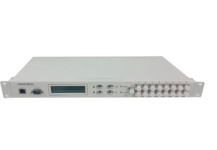
A test rack can select a channel successfully and still record the wrong optical reading if the controller samples before the route has settled. For a laboratory integrator buying from a rack mount optical switch supplier, the first requirement is the complete command-to-measurement sequence. Feiyi’s FSW-1U-1X10-MM-FCPC listing provides an 850 nm, multimode, FC/PC instrument with RS-232 and RJ45 interfaces. Confirm the ordered port map, optical conditions and command response before building the automated station.
This equipment is relevant to multi-channel optical monitoring and test systems that need controlled access to different fibers. The purchase should define the instrument, not merely a switching component inside it. An OEM assembling a controller around a bare switch and a laboratory purchasing a complete rack instrument have different interface, power and approval requirements.
Define the measurement sequence for the rack mount optical switch
The listed switching-time entry is no more than 10 ms for adjacent sequential switching. That condition matters. It should not be translated into a guaranteed end-to-end measurement delay for every route, command transport and external detector. The controller also has to receive and interpret the instrument response and coordinate the receiving equipment.
Wait for the serial response before requesting an optical reading
Feiyi states that the instrument executes one command at a time and that the program should wait for a response before sending another command. Preserve that behavior in the integration plan. A sequence that sends several channel commands without checking responses can lose the relationship between the requested channel and the recorded reading.
For a production-test engineer, the useful record associates each measurement with the instrument identity, selected channel and confirmed command result. If the detector has its own settling or averaging behavior, include it in the sequence. Do not assign the detector’s completed reading to the channel that was requested most recently unless the route and detector state have both been established.
Adjacent-channel time is not a whole-rack scan guarantee
A scan includes more than physical switching. Define channel selection, response handling, optical stabilization and measurement completion separately. The instrument’s published time is one input to that design, while the external source and receiver contribute other timing requirements. A sample qualification should exercise the sequence the buyer intends to run.
A laboratory that revisits one failed channel during a scan may use a different routing sequence from an uninterrupted adjacent-channel sweep. Include that behavior in the controller trial. A station that works only for a fixed monotonic sequence can become unreliable when a technician requests a manual recheck or changes the active channel range.
850 nm, 50/125 fiber and FC/PC belong to one instrument configuration
The FSW-1U-1X10-MM-FCPC table lists 850 nm operation, MM 50/125 µm fiber and FC/PC connectors. Keep those details connected to the ordered model. A rack-format case does not establish that the instrument can be moved to a single-mode 1550 nm test simply by changing the patch leads.
Use the multimode launch intended for the 850 nm station
Establish the source and launch lead used to qualify insertion loss. The listed instrument value is no more than 1.2 dB, with repeatability no more than ±0.02 dB. The buyer should define the reference planes and test connections before comparing those values with a complete rack path that may contain several additional connections.
An integrator serving several test benches should record the optical configuration of each bench. Identical controller software can operate instruments with different optical assemblies, but that does not make their measurements directly comparable. Keep the fiber, wavelength and connection boundary alongside the measurement sequence rather than only in a purchasing attachment.
FC/PC mating requires the correct receiving adapters
Confirm the mating polish and connector interface at the source, instrument and receiver. Do not introduce an angled-contact lead into a physical-contact arrangement because the outer connector family looks right. Clean and inspect the optical connections before a channel comparison, particularly when the rack will be connected and disconnected frequently.
The listing gives return loss of at least 30 dB, crosstalk of at least 35 dB and PDL no more than 0.05 dB. Keep the approved definitions for the selected instrument. A test of one connected channel does not establish isolation for an undefined neighboring path or performance at another wavelength.
Automatic scanning and manual channel selection need distinct operating states
Feiyi describes configurable start and end channels for automatic scanning, and a maximum switching interval of 99 hours, 59 minutes and 59 seconds. The relevant purchasing question is how the rack controller manages that scan state, especially when it interrupts the scan to select one channel manually.
The command information indicates that a current-channel setting stops automatic scanning. Incorporate this behavior into the user procedure. A technician selecting a channel for diagnosis should know whether the rack resumes the earlier scan or remains in a manually selected state. The recorded optical data should make that state visible.
Device addressing matters when one serial interface controls several instruments
The product describes a configurable device address for controlling multiple instruments through a single serial resource. Record the address assigned to each unit and associate it with the optical connections in the rack. An address collision can make a correct-looking command operate the wrong physical route.
The listed baud-rate options include 1200, 2400, 4800, 9600, 19200, 57600 and 115200. Choose the rate supported by the integration and preserve it in the configuration record. After changing a communication setting, verify the instrument identity before resuming acquisition. A successful serial connection alone does not prove the controller is talking to the expected unit.
The command conventions call for uppercase instructions and start/end delimiters. Use the approved command set for the delivered instrument, including its firmware-related information if provided. Do not assume every Feiyi optical-path instrument accepts the same command merely because the front-panel layouts look similar.
Preserve the complete exchange for the first integration trial: the command sent, response received, address and selected channel. A controller log containing only “switch complete” removes the evidence needed to distinguish an instrument response from the software’s own assumption. When acquisition fails, the retained exchange can identify whether the problem preceded optical measurement or occurred in the receiving equipment.
If the serial connection is lost, stop assigning new detector readings to requested channels until instrument state has been recovered. The last command sent is not proof of the active optical path after a communication interruption. Query the relevant state using the delivered command set, or follow the approved reset procedure, then explicitly establish the route before allowing collection to resume.
A rack shared by several operators needs a policy for front-panel intervention during a controlled scan. A person selecting a channel for diagnosis can invalidate the controller’s expected sequence even though both the instrument and detector are operating normally. Decide whether intervention is prevented, recorded or followed by a state check. This is a test-station design choice to implement and validate with the ordered instrument.
Choose the rack instrument by route architecture, not its display
Feiyi lists several instrument arrangements that merit comparison before the rack drawing is released. The FSW-1X10-U is a separate listing whose route and interface definition should be recovered for the selected build. Use it to discuss the required configuration rather than assuming its specification is identical to the MM-FCPC model.
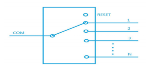
The OSW-11×10 presents a different multi-input and grouped-output arrangement. Its name should not be interpreted as proof of unrestricted connection from any input to any output. Obtain the actual group and port drawing and compare it with the paths the test station needs to reach.
The FSW-1×8-T-S desktop switch provides another instrument format for a suitable bench arrangement. It may be relevant when the station does not require the rack chassis. Moving between a desktop and rack instrument still requires an optical and controller review; similar channel-selection functions do not preserve every interface.
VIAVI’s instrumentation-switch range provides external context for treating switching as part of a measurement platform. Its modules and operating specifications remain VIAVI’s. For this rack, acceptance should follow the actual Feiyi model, route drawing and command behavior.
A 19-inch 1U housing needs space for the connected fibers
The Feiyi table identifies a 19-inch 1U chassis of 483 × 200 × 44 mm. Allocate connector access and fiber routing in addition to the metal dimensions. A rack slot that admits the chassis may still leave insufficient room to connect and service the FC/PC leads without disturbing neighboring equipment.
For a network monitoring rack, identify the panel-to-instrument patch route and where the common lead is retained. Label the instrument ports so the controller channel and physical fiber identity remain connected after a lead is replaced. A correct electronic channel number is not enough if the patch-panel association has been lost.
Before mounting neighboring equipment, confirm that a technician can release and inspect each FC/PC connection. Service access should not require pulling an unidentified fiber bundle across the front panel. Retaining a readable association between controller channel, instrument connector and patch-panel position reduces the chance that a later cable repair changes the optical route while leaving the software configuration untouched.
The instrument lists a single AC supply of 85–264 V at 50/60 Hz, operating temperature of −5 to +60°C and storage temperature of −40 to +80°C. Compare these entries with the actual cabinet conditions and ordered power interface. Do not infer redundant power, an environmental qualification or a particular supplied cable from the existence of a rack housing.
Approve the optical switch with the controller that will use it
Receiving qualification should begin with the delivered model and configuration identifiers. Establish communication, query the instrument state using its approved commands, and confirm that the requested route reaches the labeled optical connection. Repeat this across the needed channel range instead of relying on a single manually selected path.
Then exercise the intended acquisition sequence with the actual source and receiver. Include a scan interruption and the defined recovery procedure if the station will permit manual intervention. Record when a result is rejected or retried after an unexpected response, so invalid data cannot enter the output as an apparently normal channel measurement.
For shipping, specify protection for the chassis and optical interfaces, together with identification of any delivered leads or accessories. Agree the documentation and configuration record that accompany the unit. This is an equipment-specific request, not a promise that every instrument is held in stock or ships with a particular packing arrangement.
Feiyi’s installed-route replacement guide covers a different task: preserving an existing switch path. For the automated rack, release the order only when the instrument map, communication state and measurement sequence are resolved together. The station should know which fiber it is measuring before it records a number.