PM Optical Circulator Supplier: Resolve the Return Path in a 1550 nm Sensor
A returned signal can be weak even when the outgoing laser power looks normal. In a polarization-sensitive fiber sensor, the source, the returning light and the detector need different optical routes, while the polarization reference must remain consistent. A PM optical circulator supplier should therefore be evaluated against your actual port map and operating wavelength before you compare component prices. Start with Feiyi’s PM 1550 nm circulator for a 1550 nm design, or the PM 1310 nm version when the instrument operates in that band.
A PM optical circulator supplier needs the sensor’s outgoing and returning routes
Consider an integrator building an interrogator in which one fiber carries illumination toward a sensing element and brings reflected light back. A simple power splitter sends some outgoing light toward a second branch, but it does not perform the same directional routing as a circulator. The PM circulator’s job is to move the launch from Port 1 toward Port 2 and direct the light returning to Port 2 toward Port 3. That makes the detector path explicit instead of relying on an assumed split.
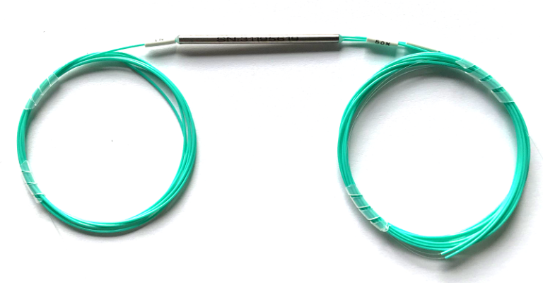
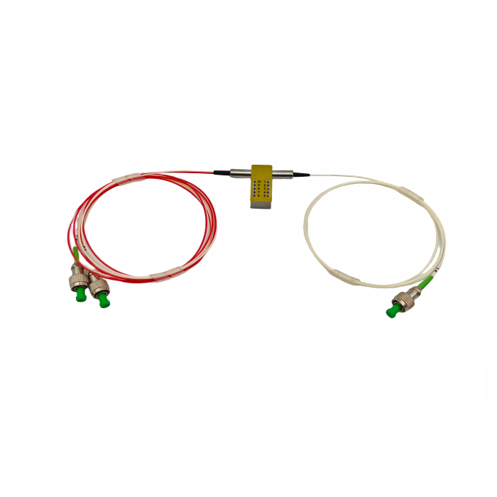
Feiyi’s 1550 nm product specifies a Port 1-to-Port 2-to-Port 3 configuration and PM1550 fiber. Its listed applications include fiber sensors, optical instruments and bidirectional communication. These details make it a relevant starting point for the proposed route, but they do not determine how much receiver leakage your particular detector can tolerate. Mark the source output, expected sensor return and any connector reflections on the instrument drawing before choosing a single-stage or double-stage device.
Three-port PM routing is different from laser back-reflection protection
A circulator separates paths; an isolator suppresses reverse transmission along a source-protection path. Feiyi’s PM 1310/1550 nm fiber optic isolator is a separate product family with single-stage and dual-stage options. It may be relevant elsewhere in the instrument, but adding it without drawing its position can block a return that the sensor actually needs. Put source protection and return collection on the same optical diagram, then establish which direction must remain open at each component.
The directional distinction also appears in Agiltron’s PM circulator documentation, which describes nonreciprocal routing while maintaining polarization. This is useful background for interpreting a supplier drawing, rather than a substitute for the specifications of the Feiyi device you order.
PM circulator stage selection changes isolation and the available signal budget
Feiyi lists both single-stage and double-stage configurations for its 1550 nm PM circulator. The wavelength is stated as 1550 ±30 nm, and the listed minimum extinction ratio is 20 dB for both configurations. The stage choice should therefore be driven by the leakage path that matters in the instrument, rather than by assuming that every optical characteristic improves by the same amount when another stage is added.
| 1550 nm configuration | Listed typical isolation | Listed minimum isolation | Listed maximum insertion loss |
|---|---|---|---|
| Single stage | At least 30 dB | At least 22 dB | 0.9 dB |
| Double stage | At least 46 dB | At least 40 dB | 1.0 dB |
Use the minimum isolation value when you establish an acceptance requirement. A typical value describes an expected operating point and should not silently become the contractual limit for every delivered device. Likewise, the listed maximum insertion loss is a component specification; connectors, splices and the remaining instrument path contribute additional losses. Confirm the measurement wavelength, temperature, launch axis and connector condition with the supplier before treating these figures as a complete channel budget.
1550 nm isolation and extinction ratio answer different detector questions
Isolation concerns unwanted propagation between optical directions or ports. Extinction ratio concerns the relationship between the intended and unwanted polarization components. A detector may receive enough total power while the desired polarization contribution is too small, or it may see unwanted source leakage despite adequate polarization preservation. Record both requirements separately so that an acceptable reading in one test cannot conceal a failure in the other.
The Feiyi 1550 nm product also lists a maximum power handling of 300 mW. That figure should stay attached to this product and its agreed operating conditions. It is not permission to route an arbitrary pulsed laser, amplifier transient or higher-power source through the same assembly. If the project has short pulses or abnormal startup conditions, include those characteristics in the review instead of describing the source only by average power.
A 1550 ±30 nm operating band still needs a wavelength-specific acceptance condition
A sensor using a tunable source should identify its actual sweep endpoints, not simply write 1550 nm on the order. The listed operating band describes the product range, while the acceptance agreement must say where isolation and insertion loss are to be checked. If the receiver is most vulnerable near one end of the sweep, include that point in the sample evaluation. A convenient center-wavelength measurement cannot establish every condition across a swept instrument.
Apply the same reasoning when comparing the separate 1310 nm product. Its table identifies 1310 ±30 nm and PM1310 fiber, which distinguish it from the 1550 nm assembly even when the package options look similar. Keep the wavelength and fiber designation together on the order and on incoming identification. That prevents a mechanical replacement from becoming an unintended optical substitution.
PM1550 fiber and connector orientation must describe one continuous polarization reference
The same connector shape does not guarantee the same PM-axis orientation. Feiyi’s circulator ordering information includes connector choices such as FC/PC and FC/APC, and its product table identifies fast-axis and slow-axis working options. Those choices have to agree with the connected source, sensing assembly and receiver. Define the intended axis at each interface rather than leaving the receiver team to infer it from a cable label.
FC/APC PM connections need both polish compatibility and an axis agreement
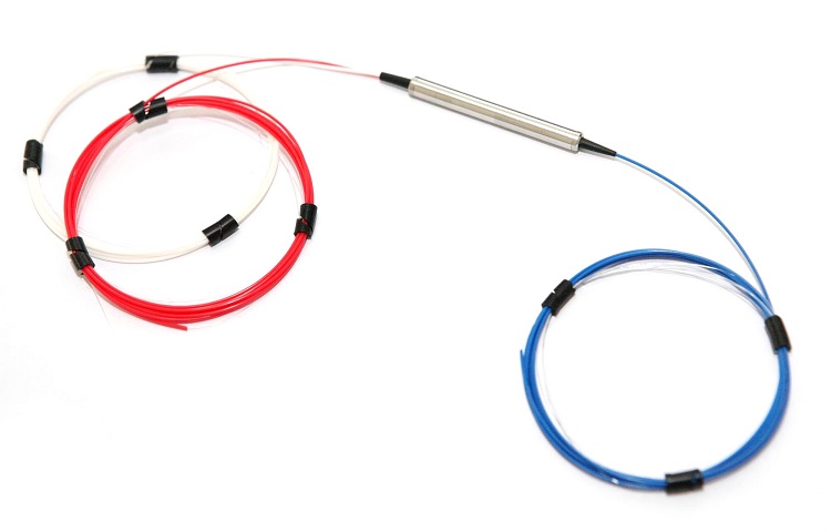
A project using FC/APC should specify that interface through the mating adapters and jumper ends, rather than selecting FC/PC at one location because the connector body looks familiar. The polish choice and the PM-axis choice are separate requirements. Feiyi’s PM 1550 nm optical patch cord lists PM1550 fiber and fast-axis, slow-axis or customized orientation options, making it relevant to the external connections around the circulator.
OZ Optics’ PM connector guidance explains why the polarization axis must be referenced to the connector key. For procurement, the useful consequence is specific: the jumper specification should state which axis the key represents, whether that convention is the same at both ends, and which adapter will be used during acceptance. Do not replace those fields with the general phrase “PM compatible.”
For an OEM adapting a 1310 nm instrument to 1550 nm, retaining every existing jumper can be a tempting shortcut. Feiyi offers separate 1310 nm and 1550 nm PM circulator products with corresponding PM fiber designations. Review the complete wavelength route, including jumpers and any source isolator, before approving the substitution. A changed source wavelength is a reason to reopen the optical bill of materials, not merely to edit the circulator’s name.
Test the PM circulator inside the connection arrangement you plan to build
A useful sample evaluation has two stages. First, confirm the supplied device against its agreed component specification. Then evaluate it with the actual connectors, adapters and PM jumpers used by the instrument. This separates a device problem from a connection problem and prevents the supplier’s bare-fiber result from being compared directly with an assembled route containing several additional interfaces.
For the 1550 nm sensor route, measure the intended Port 1-to-Port 2 and Port 2-to-Port 3 paths under the agreed launch conditions. Separately measure the unwanted route relevant to receiver contamination. Document the source wavelength and launch axis, and check the polarization at the receiver end after connecting the selected PM jumper. These are proposed acceptance steps, not a claim that Feiyi performs this exact instrument-level test for every order.
A connector remating trial can separate PM-jumper alignment from circulator behavior
If the receiver reading changes after the assembly is reconnected, repeat the connection test with a stable reference jumper and inspect the adapter and connector faces. Avoid changing the circulator, the source launch and the jumper simultaneously: the result would not identify which interface caused the change. Record the remating sequence and the measured values so the optical and purchasing teams can discuss the same event.
Thorlabs’ PM connector information illustrates the importance of connector-key and mating-slot compatibility. The general connection lesson applies to the test arrangement, but its product-specific tolerances should not be copied into a Feiyi purchase specification. Obtain the tolerance and key convention for the actual supplied jumper and adapter.
Protect the approved interfaces when the samples leave the test bench. For a connectorized circulator order, request protected connector ends, individually identifiable leads and a packing arrangement that keeps the fiber loops from being crushed by the metal housing. If one lot combines 1310 nm and 1550 nm variants, require identification that distinguishes them without relying on lead color. Agree these packing instructions with the supplier; the product listing does not establish a standard export carton or a fixed shipping schedule.
Agree the 1550 nm circulator configuration before the repeat order
The sample that performed well should translate into a complete configuration record: wavelength band, single or double stage, PM fiber type, working axis, port identification, connectors, lead length and the acceptance conditions. Feiyi lists cylindrical package options and an ABS-box option on the 1550 nm product, so mechanical integration belongs in that record too. Confirm the selected housing against the enclosure drawing rather than assuming that any listed package fits the same mounting space.
The listed cylindrical options include 5.5 mm diameter housings with 35 mm or 50 mm length, while the ABS option is listed as 90 ×20 ×10 mm. Allocate room for the fiber exits and the jumper connection rather than treating the metal housing dimensions as the entire installation envelope. A routing drawing should show which lead reaches the source and which reaches the detector without pulling a tight loop across the component body.
Lead length also affects that integration decision. The ordering information lists examples of 0.5 m, 1 m and 2 m. Specify the length needed by the actual sensor enclosure and identify whether it refers to each lead; do not assume a published example is the default delivered length. For a repeat build, a longer lead may be manageable, but a shorter detector lead can force an extra connection and change the very acceptance route already approved.
Read Feiyi’s discussion of PM circulator applications when comparing the instrument’s routing needs with other uses. For broader PM-fiber behavior, Corning’s PANDA fiber information provides background on polarization-maintaining fiber; it does not certify the assembled instrument’s performance.
Before releasing the order, put the receiver leakage limit beside the PM-axis drawing and the agreed 1550 nm configuration. If the double-stage sample solves the leakage problem and the connected jumper preserves the required axis, approve that combination as a unit. If either remains unresolved, keep the sample evaluation open. The most useful supplier decision is the one your engineering team can reproduce in the next assembled sensor.