
Qualifying a PM Fiber Pigtail Supplier for Single-Fiber and Multi-Fiber Assemblies
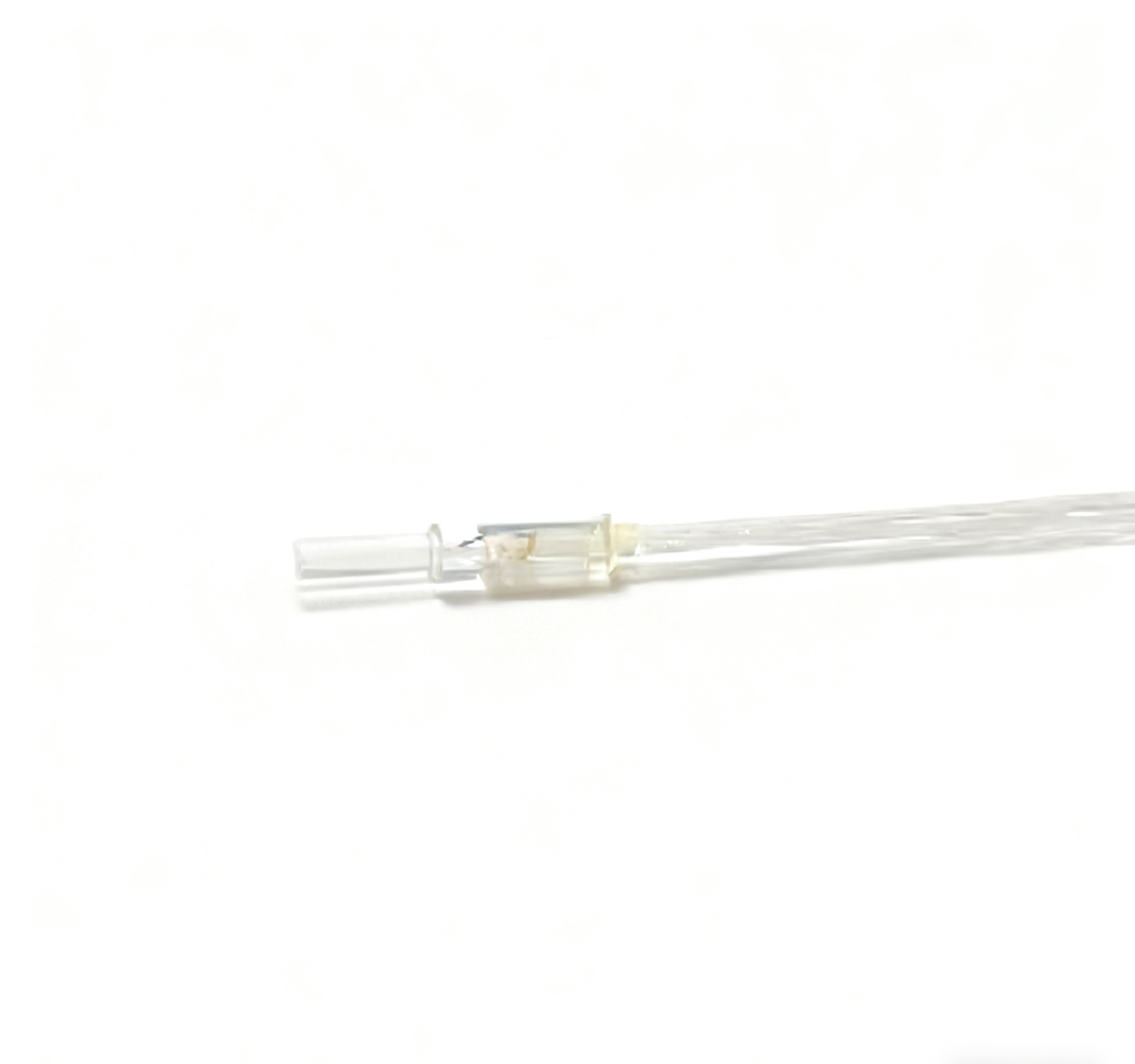
“Pigtail” can describe a connector-ended fiber, but it can also describe the small ferrule-and-fiber assembly built into a micro-optic component. Those descriptions are not interchangeable. An OEM comparing a PM fiber pigtail supplier should first define the optical end that enters its assembly: ferrule size, fiber count, end geometry, channel positions and polarization-axis reference. Feiyi’s custom PM single-fiber pigtails and PM dual-fiber pigtails are useful starting points for this component-level work. Confirm the assembly interface before discussing the remote connector or deciding how many units to stock.
A PM fiber pigtail supplier needs the ferrule interface, not only the cable end
Feiyi’s pigtail range identifies compact ferrule dimensions and application areas including isolators, circulators, switches and WDM. Those uses place the pigtail inside an optical assembly decision. The buyer must establish how its optical end meets the adjoining optics, while the remote fiber lead may later receive a connector or splice. A fiber-count label does not define that optical end.
The custom PM single-fiber pigtail offers two compact ferrule diameters
The custom single-fiber listing gives 1.8 ×6.5 mm and 1.0 ×6.5 mm dimension choices. Select the relevant diameter against the mounting seat and optical layout. A smaller ferrule should not be approved solely because it saves space if the fixture, alignment method or mating arrangement was developed for the larger version. The accepted drawing needs to identify the chosen physical construction.
The same product separates P-grade and A-grade loss and return-loss entries. Its typical insertion losses are 0.18 and 0.2 dB, with maximum entries of 0.21 and 0.25 dB respectively. Its return-loss entries are 65 and 62 dB. These published distinctions support a grade-specific discussion; they do not prove that either grade will meet an unspecified complete component’s coupling loss.
A component maker designing an isolator housing can use the pigtail information to narrow a mechanical and optical interface. The final isolator still has its own optics and acceptance requirements. Keep the pigtail test boundary separate from the finished component’s test boundary, so that a ferrule-level result is not represented as an assembled isolator result.
OZ Optics’ optoelectronic-packaging overview distinguishes fiber ferrules, fiber assemblies and collimation components as separate building blocks. That general distinction is helpful here. It does not establish that Feiyi uses another company’s sealing methods, materials or manufacturing processes.
PM pigtail fiber count changes the channel definition inside one ferrule
Moving from one fiber to two or more fibers adds channel-position and identification questions. Feiyi lists PM single-fiber pigtails, dual-fiber pigtails, PM four-fiber pigtails and PM sixteen-fiber pigtails. Their count is a useful family distinction, but it does not provide an approved channel-coordinate drawing by itself.
A dual-fiber PM pigtail requires a reference for both fiber axes
An OEM adding a dual-fiber end to a micro-optic assembly should identify each fiber position and how its PM axis relates to the ferrule reference. The axis of one channel should not be presumed to define the other automatically. If the assembly sends and receives light through different fibers, preserve that physical identification from the drawing to the remote ends.
Ask for the end-face view and the direction from which it is drawn. A channel map viewed from the optical face can be reversed relative to a view from the lead side. Agree the indexing convention and mark an unambiguous physical reference. This is particularly valuable when the small ferrule’s exterior provides few obvious orientation features.
PM Optics’ fiber-array information illustrates that fiber type, channel geometry and pitch are separate specification topics. Do not assign its pitch, tolerance or channel capacity to a Feiyi pigtail. Request the geometry that fits the actual mating optics, then approve the supplier’s drawing for the selected build.
For a four-channel optical subassembly, the channel map may be more important than having four identical connector ends. The receiving technician needs to know which lead belongs to each end-face position. A label sequence without the agreed viewing direction can still produce a wrong assembly. Keep the drawing, lead identifiers and intended optical destinations together.
Do not give every PM pigtail format the same extinction-ratio requirement
Feiyi’s standard single-fiber pigtail lists extinction ratio of at least 22 dB, its dual-fiber version at least 20 dB and its four-fiber version at least 18 dB. The sixteen-fiber listing gives at least 16 dB. Those values show why “PM pigtail” is not a complete optical-performance description across the family.
| Published PM pigtail format | Listed extinction ratio | What the assembly approval must retain |
|---|---|---|
| Standard single fiber | ≥22 dB | One identified optical channel and its axis |
| Dual fiber | ≥20 dB | Two positions and their individual axis references |
| Four fibers | ≥18 dB | Four-channel map and agreed per-channel acceptance |
| Sixteen fibers | ≥16 dB | Complete channel identification and the applicable delivered-assembly test |
A sixteen-fiber PM assembly needs channel-level acceptance rather than one average
A satisfactory average can conceal a channel that does not meet the instrument’s requirement. Ask how the selected sixteen-fiber construction will be evaluated and which results belong to each identified channel. Define whether the requirement applies to all channels and which launch condition and reference connections will be used. The catalog value should remain attached to its actual measurement definition.
A distributor receiving both single-fiber and sixteen-fiber orders should preserve these distinctions in its part descriptions. A similar 1.8 mm ferrule dimension does not make the optical requirements identical. Keep fiber count, wavelength, PM fiber and extinction-ratio acceptance visible so a replacement order does not inherit the wrong family value.
The custom single-fiber pigtail separately lists an extinction ratio of at least 23 dB. Its grade structure and operating range also differ from the standard single-fiber listing. Treat it as a selected construction with its own agreed specification, rather than using the highest entry found anywhere in the range as a universal claim.
Match the PM pigtail wavelength and axis to the adjoining optical element
The standard single-, dual- and multi-fiber listings include wavelength choices from 630 through 1550 nm and corresponding PM630, PM780, PM850, PM980, PM1060, PM1310 and PM1550 fiber designations. Select the applicable combination against the actual operating spectrum. The connector shape or ferrule diameter does not identify the wavelength variant.
PM1060 and PM1550 belong to different wavelength decisions
A buyer building a 1064 nm assembly should identify the approved PM1060 route, while a 1550 nm assembly should identify its PM1550 route. Keep the relevant fiber designation and operating wavelength together. If a project contains both wavelength bands, separate their order lines and optical destinations rather than using one “PM fiber” description for all channels.
Fujikura’s PANDA-fiber overview shows why polarization-maintaining fibers are offered for different wavelength and handling requirements. Its fiber specifications are background information, not proof of the exact fiber manufacturer or bend radius in a Feiyi assembly. Obtain the selected pigtail’s approved fiber identity and handling limits.
Feiyi’s standard pigtail listings include fast- and slow-axis choices. Tie that choice to the optical element and the mechanical reference of the ferrule. A remote connector’s key may help preserve an axis reference, but it does not establish the orientation at a multi-fiber optical end unless the complete assembly drawing defines that relationship.
If the remote leads will be fusion-spliced, tell the assembly engineer which fiber and axis references must continue through the splice. Fujikura’s specialty-splicing information identifies PM alignment as a distinct capability. Do not assume that a standard single-mode splice procedure is sufficient for the required PM interface, or that Feiyi supplies a particular splicer or completed splice process.
The lithium niobate pigtail module requires its own optical-end definition
Feiyi’s lithium niobate pigtail module is another component interface to review where the adjoining optical design calls for it. Its listing includes a 1.8 ×6.5 mm dimension, PM980/PM1550/PM1310 fiber options and extinction ratio of at least 25 dB. Those entries provide starting details for a pigtail assembly discussion.
The name does not establish that the supplied item is a complete active lithium niobate modulator, an integrated electronic driver or a guaranteed chip-coupling solution. Describe the receiving optical surface and required fiber-end construction to the supplier. Confirm the module’s scope and the delivered interface rather than transferring expectations from a complete modulator to a pigtail component.
The lithium niobate pigtail and custom single-fiber listings show 0.5, 1 and 2 m lead-length choices. Identify the length reference from the compact optical end to the remote termination, and account for any fiber that the buyer’s assembly process will consume. A lead nominally long enough to reach a splice station may be too short after trimming and routing. For a multi-fiber item, confirm whether all leads are equal or individually defined in the accepted drawing.
For a prototype team changing the optical-end design, preserve the accepted drawing revision. A ferrule that fits mechanically can still have the wrong end geometry or fiber-to-optic relationship. Ask which interface dimensions and optical conditions are controlled in the supplied assembly, and decide which aspects will be established during the buyer’s own integration process.
Keep the PM pigtail’s optical face protected until the assembly fixture is ready
The exposed optical end deserves different handling from a conventional connector under a dust cap. Request a protective arrangement appropriate to the selected ferrule and end geometry, with support that avoids placing tension on the remote fibers. Do not assume that protection suitable for a connector also protects an exposed multi-fiber end. The approved packing request should identify which surface must remain untouched.
Feiyi’s standard pigtail listings give an operating range of +10 to +60°C and a storage range of 0 to +85°C, while its custom single-fiber listing gives different ranges. Keep the selected product’s condition in the assembly plan. If the process includes heating, bonding or exposure beyond the listed environment, obtain explicit process approval; the existence of a storage-temperature value does not qualify every assembly operation.
At receiving, reconcile the ferrule dimension, fiber count, wavelength, lead labels and connector choices with the accepted drawing before removing the optical-end protection. For multi-fiber work, check that the channel-identification method survives the next assembly step. Receiving confirmation should preserve the supplier’s component identity without inventing a new axis convention in the workshop.
The pigtail listings include a 500 mW maximum power-handling entry. For a multi-fiber assembly, ask how the rating applies to the selected construction and its intended illuminated channels. Do not assume it is a separately additive allowance for every fiber. An array carrying several sources requires an agreed power condition for its optical end and materials, just as the channel map requires an agreed physical reference.
The existing Feiyi guide to regular and PM pigtails provides a broader fiber-type comparison. For this order, the decisive document is the actual ferrule and channel drawing. Approve that optical end, its PM references and its test boundary first; then the remote leads and order quantity can be specified around a defined assembly interface.