Tapered Lensed Fiber Manufacturer: Qualify the Apex Angle by the Optical Field
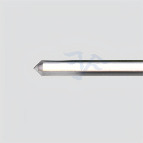
A buyer searching for a tapered lensed fiber manufacturer should treat the processed tip as an optical interface, not as a generic piece of fiber with a pointed end. Feiyi’s Tapered Lensed Fiber page publishes a ring-shaped far-field spot, a 60-120 degree apex-angle range, SM/MM/PM/custom fiber options and customizable fiber and stripped-coating lengths. Those details make the right starting point a target beam and coupling condition.
A tapered tip can be used for beam expansion, endoscope illumination and fiber-laser coupling output for DFB lasers according to Feiyi’s page. Those applications do not use the same optical acceptance test. A buyer should therefore define the intended field, wavelength, raw fiber, mechanical length and whether a connector or coating is required before approving the tip geometry.
A tapered lensed fiber manufacturer needs the far-field target before the apex angle is frozen
Feiyi publishes a 60-120 degree apex-angle window for its tapered lensed fiber. That range is a manufacturing option, not a promise that every angle creates the same beam. The page identifies a ring-shaped far-field spot for the family, so the engineer should specify the desired ring or coupling behavior and use the apex angle as one controlled variable.
The 60-120 degree apex range should be tied to the coupling setup
If a DFB laser is being coupled into fiber, the emitter geometry, working distance and target overlap influence which processed tip is useful. If the same tapered fiber is used for beam expansion, the acceptance condition may be a measured far-field shape rather than coupling efficiency into a particular emitter. The manufacturer needs to know which problem is being solved.
For sample approval, record the requested apex angle, raw fiber and test wavelength together. A repeat lot described only as “tapered lensed fiber” leaves out the geometry that produced the accepted result.
Ring-shaped output is a different design target from flat-top or rectangular spots
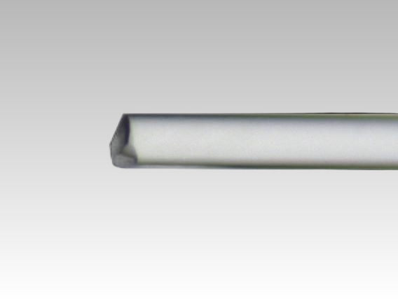
Feiyi’s lensed-fiber family gives useful comparisons. Its Two-Faceted Lensed Fiber is published with a flat-top far-field pattern, while the Four-Faceted/Pyramidal Lensed Fiber is published with a rectangular spot. The tapered product is published with a ring-shaped far field. Those are materially different optical outputs.
An engineer who actually needs a flat-top illumination field should not force a tapered geometry into the design simply because it is familiar. Likewise, a rectangular emitter-coupling problem may point toward a faceted geometry. A tapered lensed fiber is appropriate when its output-field behavior fits the real system.
Tapered lensed fiber manufacturer selection begins with SM, MM or PM raw fiber
Feiyi lists single-mode, multimode, polarization-maintaining and customized raw-fiber options for the tapered product. That choice affects modal behavior before the taper is processed. It should be made from the optical source and application rather than from the connector that will later be added.
Single-mode tapered fiber suits a different coupling problem from multimode illumination
A single-mode source and receiver depend on spatial-mode overlap, so the processed tip has to support efficient coupling of the intended fundamental mode. A multimode illumination application can tolerate or even require a different field distribution. The same apex angle should not be assumed to produce an equivalent system result across SM and MM fiber.
For purchasing, put the base-fiber specification at the top of the drawing. Connector style and jacket choices can follow. This prevents a mechanically correct assembly from being built on the wrong optical fiber.
PM tapered lensed fiber adds rotational axis control to the tip geometry
When PM fiber is selected, the polarization axis becomes part of the component definition. The engineer should state which axis carries the intended launch and how that axis relates to any external connector or mechanical reference. The tip then has to satisfy both the required spatial field and the required polarization orientation.
This is especially important if the tapered fiber connects directly to a PM isolator, circulator, polarizer or waveguide. All of those interfaces should use a consistent axis convention. Feiyi’s PM patch-cord axis article provides a useful reference for the general handoff problem, even though the lensed tip itself is a different component.
Direct bare-fiber processing changes how the tapered tip should be inspected
Feiyi states that the tapered lensed fiber can be processed directly on bare fiber without auxiliary adhesives, with no organic residue from an added bonding material at the processed tip. That construction detail matters for cleanliness-sensitive optical interfaces because the manufactured optical surface is formed directly on the fiber.
Visual inspection should look for the processed tip and contamination separately
A microscope image can confirm that the taper is present and can reveal obvious contamination or damage, but it cannot by itself confirm the far-field result. Incoming inspection should separate those questions. First check the physical condition of the tip; then perform the optical measurement that corresponds to the approved application.
For a fiber-laser coupling sample, that may mean measuring coupling or output behavior in the defined fixture. For an illumination product, it may mean recording the far-field pattern at a defined distance. The test should be chosen because it represents the product’s job.
Stripped-coating length should be treated as a mechanical interface dimension
Feiyi states that fiber length and stripped-coating length can be customized. Those dimensions affect how the lensed fiber is mounted, bonded or routed into an OEM assembly. A buyer should place them on the mechanical drawing rather than leave them to production interpretation.
In a compact laser module, too much stripped bare fiber can make handling difficult. Too little may prevent the fiber from reaching the intended holder or ferrule. Once a sample is approved, preserve the stripped length with the optical tip specification.
Endface coating should be specified from the wavelength and optical interface
Feiyi’s tapered lensed-fiber page states that coating can be applied directly to the bare-fiber endface to enhance coating performance and durability. A coated tip should therefore be ordered with the wavelength and application context that drove the coating choice.
Coating and apex geometry should be approved as one configuration
If an uncoated prototype is replaced with a coated version, the buyer should treat that as a controlled change rather than assume the optical result is identical. The coating interacts with the optical interface while the taper controls the field. Both belong in the sample record.
For repeat orders, record whether the tip is coated, the applicable wavelength and the accepted geometry. If the manufacturer provides several coating options for a custom project, the purchase file should identify the selected one by the agreed drawing or specification instead of a verbal description.
Connector options change handling but do not replace the tip specification
Feiyi lists optional FC, LC, SC and SMA connectors with PC/APC choices for the tapered lensed fiber. Connectorization can make a lensed fiber easier to integrate into a removable assembly, but the connector does not define the lensed end on the opposite side.
Connector polish should be selected from the mating interface, not the lensed output
An FC/APC interface may be appropriate where reflection at the connector is a concern, while another system may need FC/PC, LC or SMA for mechanical compatibility. The buyer should specify the mating hardware and reflection requirement. The tapered tip and the connector end solve different interface problems within the same assembly.
For a bare-fiber OEM integration, a connector may not be needed at all. In that case, fiber length, stripped length and protection during handling become more important. A manufacturer should not have to infer those choices from the lensed-tip geometry.
Environmental ratings are a baseline, not a substitute for application qualification
Feiyi publishes an operating-temperature range of -40 to +85 deg C and relative humidity from 0 to 85 percent for the tapered product. The page also states compliance with Telcordia GR-1221 and GR-63 Core environmental or reliability testing.
Those limits are useful when screening a manufacturer, but an endoscope illumination assembly, DFB-laser module and industrial optical sensor can have very different cleanliness, vibration or mechanical-load requirements. The buyer should add application-specific qualification where the final system demands it.
Three buyer scenarios expose different tapered-fiber priorities
For a DFB-laser coupling module, the project may be dominated by overlap between the emitter field and the shaped fiber output. The buyer should therefore preserve the source wavelength, emitter condition and working geometry used to accept the sample. For endoscope illumination, the field distribution and mechanical routing can matter more than optimizing coupling to a small semiconductor emitter. For a beam-expansion application, the far-field shape itself may be the primary deliverable.
The same tapered tip should not be accepted with one generic pass/fail test
Those three scenarios show why a manufacturer cannot be qualified only through a drawing of the apex. The laser-module team may measure coupled power, the illumination team may inspect field uniformity or distribution, and the beam-expansion team may measure the ring pattern at a defined distance. Each test is valid because it follows the intended use.
A distributor receiving multiple tapered-fiber programs should keep those acceptance records separate even if the outer packaging looks identical. Product code, base fiber, apex angle, coating and application-specific test condition together identify the approved configuration more reliably than a visual description.
Sample acceptance should preserve the field measurement that made the taper successful
A tapered lensed fiber is especially vulnerable to incomplete sample records. If the accepted sample is saved only as a microscope photograph and cable length, the team may lose the actual optical result that justified the geometry. Preserve the test wavelength, launch condition, measurement distance and the far-field or coupling metric that was accepted.
Production repeatability should be compared against the approved optical result
When a repeat lot arrives, measure a defined sample set using the same fixture and method. If the field changes, compare the geometry and raw fiber before changing the system. If the measured field is stable but system coupling changed, investigate alignment or the receiving component. This separates a lensed-fiber process issue from an assembly issue.
The approach is more useful than asking whether every tip “looks the same,” because small geometric differences matter only insofar as they change the required optical behavior.
Use the tapered geometry only when the required field points to it
Feiyi’s Tapered Lensed Fiber is the direct starting point for ring-shaped far-field and tapered-tip applications. Buyers who need a flat-top field can compare the Two-Faceted Lensed Fiber, while a rectangular field can lead to the Four-Faceted/Pyramidal Lensed Fiber. Beam-deflection requirements can be reviewed against the Angled Lensed Fiber.
The broader lensed-fiber geometry guide compares those families. For a tapered order, the actionable specification remains narrow: base fiber, wavelength, apex angle, desired field, fiber and stripped lengths, coating, connector and the optical test used to approve the sample.